5-33
1-6. SYSTEM CONTROL SYSTEM ADJUSTMENTS
1. Battery Down Adjustment
Set the battery end voltage.
If the voltage is incorrect, the life of battery will shorten.
The image at the battery end will also be rough.
Mode STILL
Subject All black (Cover the lens with a
black cap)
Measurement Point Displayed data of page: 2,
address: 51
Measuring Instrument Adjusting remote commander
Adjustment Page D
Adjustment Address 30 to 34
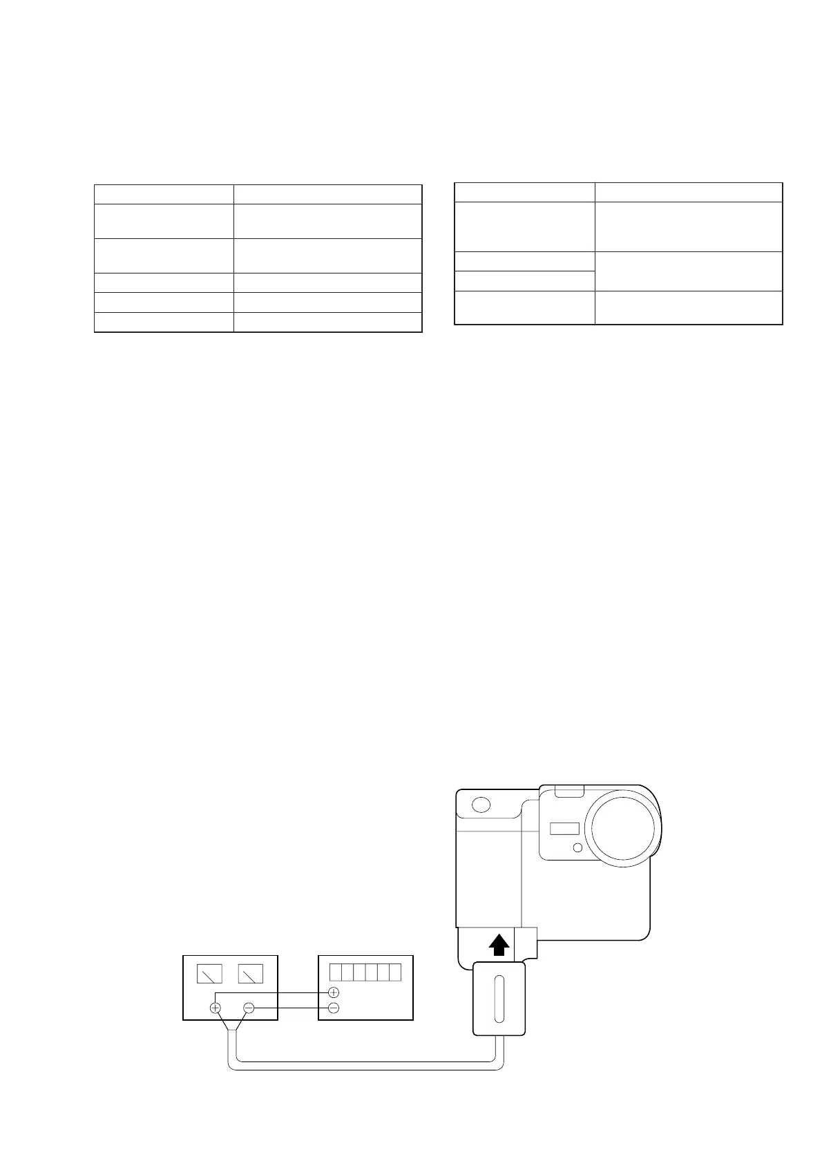
Connection:
1) Connect the regulated power supply and the digital voltmeter
to the battery terminal as shown in Fig. 5-1-28.
Adjusting method:
1) Adjust the output voltage of the regulated power supply so
that the digital volt meter display is 6.1 ± 0.1 Vdc.
2) Turn the HOLD switch of the adjusting remote commander.
3) Turn on the power.
4) Select page: 0, address: 01, and set data: 01.
5) Decrease the output voltage of the regulated power supply so
that the digital voltmeter display is 5.80 ± 0.01 Vdc.
6) Select page: 2, address: 51, read the data, and this data is named
Dref.
7) Select page: D, address: 30, set data Dref, and then press the
PAUSE button of adjusting remote commander.
8) Convert Dref to decimal notation, and obtain Dref’.
(Refer to Table 5-2-1. “Hexadecimal-decimal conversion
table”)
9) Calculate D31, D32, D33 and D34 using following equations
(decimal calculation), convert it to a hexadecimal number, and
input each adjustment address.
Address: 31 D31’=Dref’+8
Address: 32 D31’=Dref’+23
Address: 33 D31’=Dref’+44
Address: 34 D31’=Dref’+55
Note: After setting each data, be sure to press the PAUSE but-
ton.
Processing after Completing Adjustments:
1) Select page: 0, address: 01, and set data: 00.
2. Alignment Check (FDD Unit)
Confirm that the FDD alignment is within the specifications.
If deviated, reading and writing data from and to floppy disk be-
come impossible.
Or compatibility of floppy disk with other machines can be lost.
Mode PLAY
Signal Alignment disks (TFD2-1 (+))
and (TFD2-1 (-)):
Arbitrary signal
Measurement Point Check on LCD screen
Measuring Instrument
Specified Value The playback pictures should be
normal
Checking method:
1) Disconnect the adjusting remote commander.
2) Insert the alignment disk TFD2-1 (+) (+17.5 um).
3) Playback arbitrary signal and check that the playback picture
is normal.
4) Insert the alignment disk TFD2-1 (–) (–17.5 um).
5) Playback arbitrary signal and check that the playback picture
is normal.
Regulated power supply
5.80 ± 0.01 Vdc
Digital voltmeter
Power cord
(J-6082-223-A)
Fig. 5-1-28