Version 5.2 Sourcefire 3D System Installation Guide 151
Hardware Specifications
Sourcefire 7000 Series Devices
Chapter 6
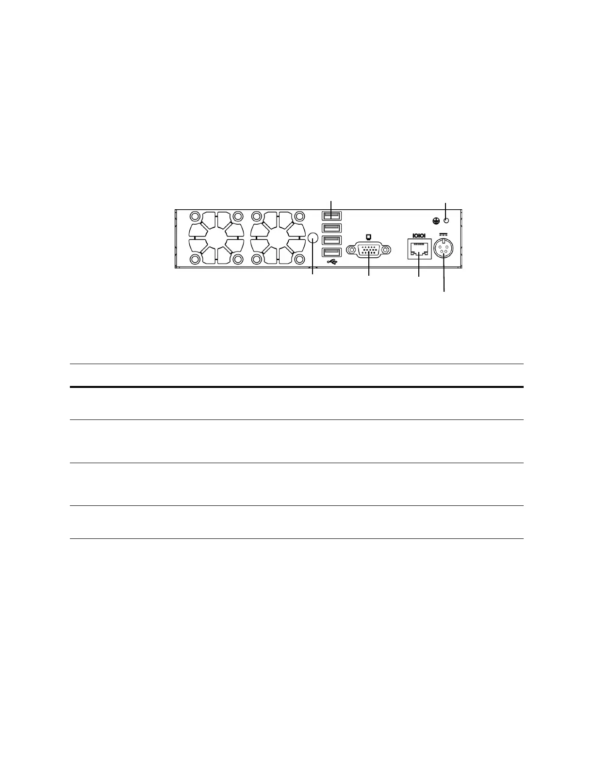
70xx Family Rear View
The rear of the chassis contains the system ID LED, connection ports, grounding
stud, and power supply connector.
70xx Family (Chassis: CHRY-1U-AC) Rear View
The 70xx Family System Components: Rear View table describes the features
that appear on the rear of the appliance.
System ID LED VGA Port Serial Port
Power Supply Connector
Grounding Stud
2.0 USB Ports
70xx Family System Components: Rear View
FEATURE DESCRIPTION
System ID LED Helps identify a system installed in a high-density rack with other similar
systems. The blue LED indicates that the ID button is pressed.
2.0 USB ports
VGA port
Serial port
Allows you to attach a monitor, keyboard, and mouse to the device, as an
alternative to using the RJ45 serial port, to establish a direct
workstation-to-appliance connection.
Grounding stud Allows you to connect the appliance to the common bonding network. See the
Power Requirements for Sourcefire Devices on page 240 for more
information.
12V Power supply
connector
Provides a power connection to the device through an AC power source.