USB full speed device interface (USB) UM0306
440/519
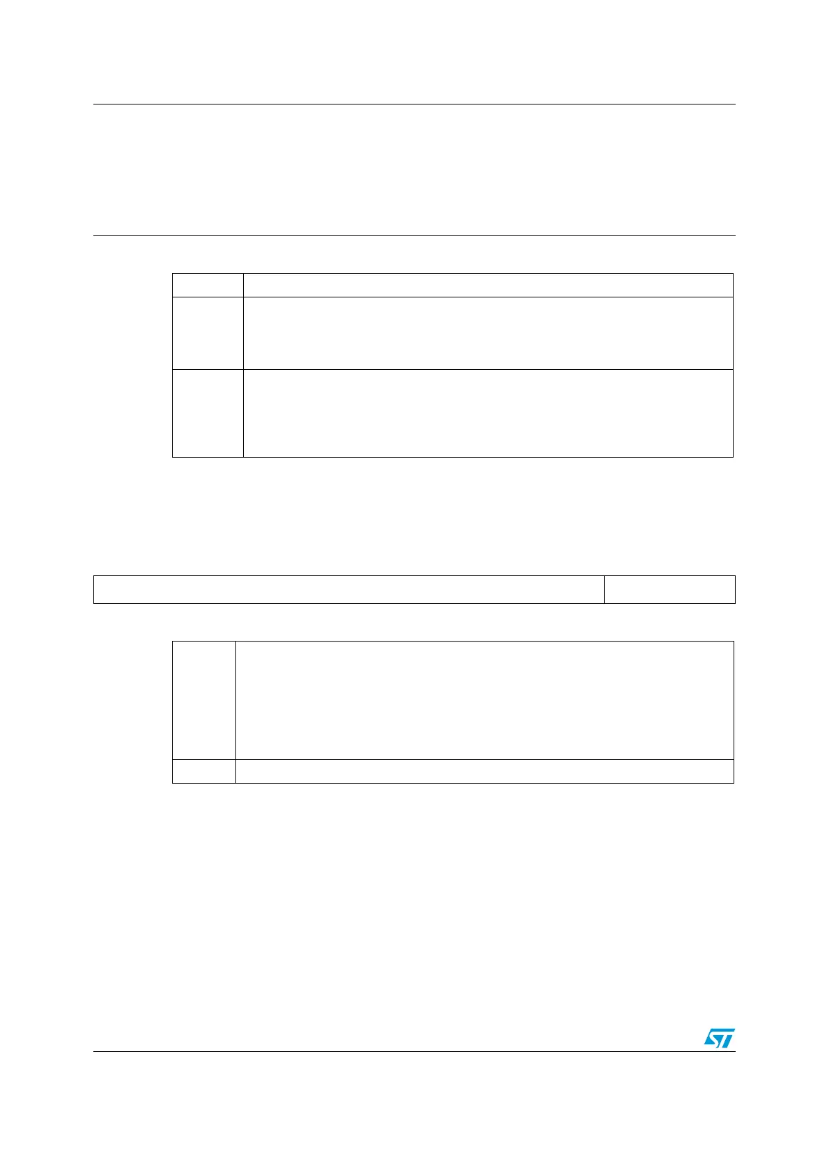
USB device address ()
Address Offset: 4Ch
Reset Value: 0000 0000 0000 0000 (0000h)
Buffer table address ()
Address Offset: 50h
Reset Value: 0000 0000 0000 0000 (0000h)
15 14 13 12 11 10 9 8 7 6 5 4 3 2 1 0
rw rw rw rw rw rw rw rw
Bit 7
EF: Enable Function
This bit is set by the software to enable the USB device. The address of this device is
contained in the following ADD[6:0] bits. If this bit is at ‘0’ no transactions are handled,
irrespective of the settings of registers.
Bits 6:0
ADD[6:0]: Device Address
These bits contain the USB function address assigned by the host PC during the
enumeration process. Both this field and the Endpoint Address (EA) field in the
associated register must match with the information contained in a USB token in
order to handle a transaction to the required endpoint.
151413121110987654321 0
BTABLE[15:3] Reserved
rw rw rw rw rw rw rw rw rw rw rw rw rw
Bits 15:3
BTABLE[15:3]: Buffer Table.
These bits contain the start address of the buffer allocation table inside the dedicated
packet memory. This table describes each endpoint buffer location and size and it must
be aligned to an 8 byte boundary (the 3 least significant bits are always ‘0’). At the
beginning of every transaction addressed to this device, the USP peripheral reads the
element of this table related to the addressed endpoint, to get its buffer start location
and the buffer size (Refer to Structure and usage of packet buffers on page 423).
Bits 2:0 Reserved, forced by hardware to 0.

 Loading...


