71TS 500i
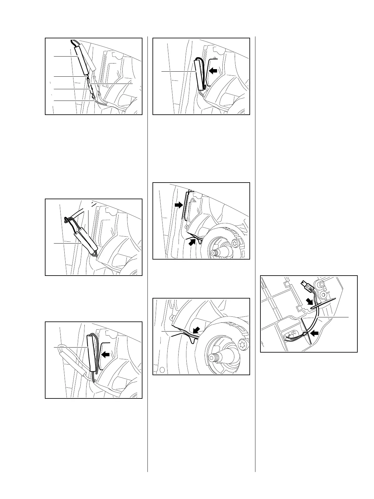
: Push the insulating tube (1) onto
the black lead (5) of the wiring
harness
: Take the plug (2) and terminal
socket (3) of the black lead (5)
and yellow lead (4) and
completely push together
: Slide insulating tubes (1) over the
middle of the plug connections,
b 1.1
: Guide the blue lead behind the
insulating tube (1) and press the
plug connection into the middle of
the guide (arrow) – the blue lead
must run underneath the
insulating tube
1307RA287 TG
1
5
3
2
4
1307RA288 TG
1
1
1307RA289 TG
1
: Guide the black lead behind the
insulating tube (1) and press the
plug connection into the middle of
the guide (arrow) – the black lead
must run underneath the
insulating tube
: Press the leads completely into
the guides (arrows)
The lead (1) must be seated
completely in the guide (arrow).
The flywheel must not touch the
generator lead
– power supply can be interrupted.
1307RA290 TG
1
1307RA291 TG1307RA279 TG
1
– Reassemble remaining parts in
reverse order
7.6 Short circuit wire / switch
7.6.1 Testing
– Test the short circuit wire / switch
with STIHL MDG 1, b 7.1,
b 7.2
– Refer also to troubleshooting
chart, b 3.5
7.6.2 Removal and installation
The switch, short circuit wire and
ground wire form a single unit. The
complete switch must be replaced if
there is any sign of damage.
– Remove shroud, b 6.4
– Remove switch shaft, b 10.1
– Remove interlock lever and
throttle trigger, b 10.2
: Pull the wiring harness (1) of the
switch on the inside out of the
guides (arrows)
1307RA292 TG
1

 Loading...