22
Info
..../ICC/more
..../ICC/more/more
EN/06.2019/G57 © STULZ GmbH – all rights reserved
C7000 INSTRUCTIONS FOR A/C UNITS
Components/Cooling
ICC
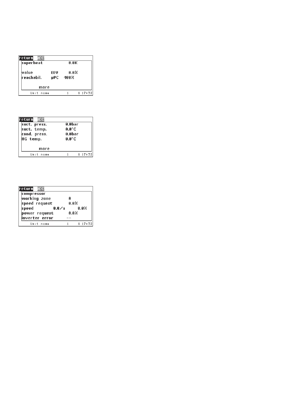
The following menus display information about the ICC (Integrated Cooling
Circuit).
The ICC controls by means of a microprocessor (µPC) board an expansion val-
ve and by an inverter a compressor.
In the first menu the superheat calculated by the µPC is displayed.
Following the opening degree for the expansion valve which is given by the
µPC and the reachability of the µPC by the RS485 bus.
In the second menu the measured values of the sensors which are connected
at the µPC are displayed. At the low pressure side of the compressor:
- suction gas pressure
- suction gas temperature
at the high pressure side:
- hot gas pressure
- hot gas temperature
The ICC working zone should be indicated as 1 in the normal case. If a higher
number appears there, The ICC will soon be in eror. See "Working zones ICC for
R410a" on the following page.
The performance requirement, which is sent by the C7000 to the µPC, is dis-
played in the penultimate line. The third line displays the speed requirement
calculated from this, that sends the µPC to the inverter. The actual speed of the
compressor will be shown in the fourth line.
The last line displays the error code if there is a malfunction of the inverter.
These sensors are part of the ICC and can
not be configured in the menu "Config/
components/sensor".
1: Overcurrent
2: Motor overload
3: Excess voltage
4: Low voltage
5: Drive temperature too high
6: Drive temperature too low
7: Hardware overcurrent
8: Motor overtemperature
9: reserved
10: CPU error
11: Parameter default
12: DC bus ripple
13: Data communication fault
14: Drive thermistor fault
Error code Cause
15: Autotune fault
16: Drive disabled
17: Motor phase fault
18: Fan fault
19: Speed fault
20: PFC module error
21: not used
22: PFC undervoltage
23: STO detection error
24: STO detection error
25: Ground fault
2698: Undefined inverter event
99: Unexpected inverter stop
Error code Cause
overcurrent
Signal detection at STO input
Signal detection at STO input
Ground current too high
PFC - power factor correction