6. Operating the infinite® 200
110 Instructions for Use for infinite® 200 No. 30017581 Rev. No. 1.4 2008-07
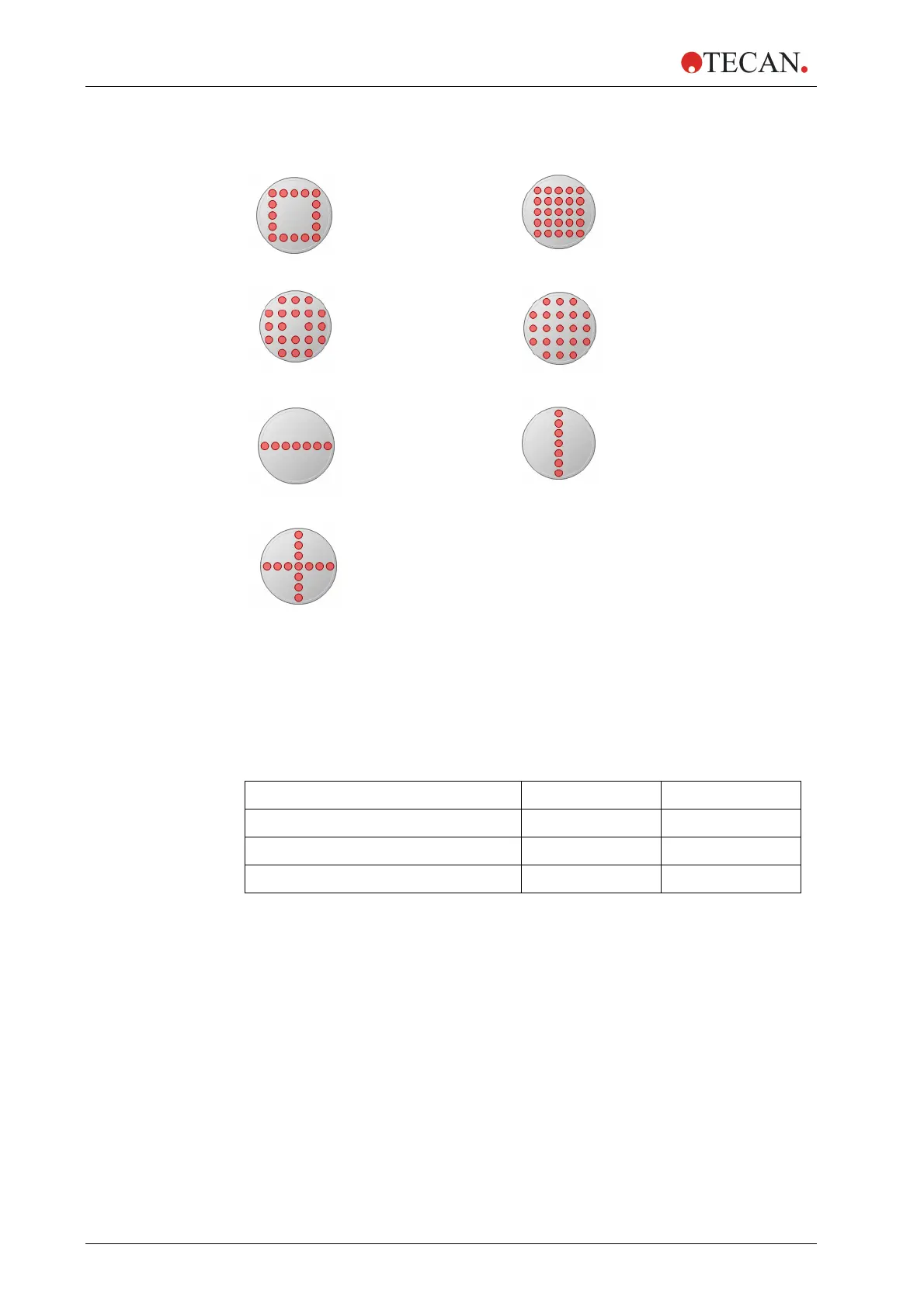
Pattern examples:
Square:
Square (filled):
Circle:
Circle (filled):
X-line:
Y-line:
XY-line:
6.6.2 MRW Size
The MRW size determines the number of points to be measured in a well.
Depending on the microplate type and instrument (
infinite
®
F200 or infinite
®
M200
) the ‘size’ is selectable from 1 x 1 to a maximum of 15 x 15 points. The
diameter of the single measurement points corresponds to the theoretically
calculated diameter of the light beam at the focal point (see Table 6.6-1).
Measu
rement Mode M200 F200
Fluorescence Intensity Top 3 mm 2 mm
Fluorescence Intensity Bottom 2 mm 2 mm
Absorbance (microplate optics) 0.7 mm 0.5 mm
Table 6.6-1: Theoretically calculated beam diameter at the focal point.
The MRW type displayed in the software is therefore only a schematic overview
of the measurement pattern. When measuring real samples the pattern can vary
and the overlap of the single measurement points can be slightly different from
the displayed pattern. It is therefore recommended to optimize the multiple reads
per well parameters for every new application.
6.6.3 MRW Border
In addition to ‘Size’ and ‘Type’, a ‘Border’ function allows the user to select a
certain distance between light beam and the wall of the microplate well
(distance in µm). As already stated in chapter 6.6.2, the software displays only a
schem
atic overview of the measurement pattern. The border is calculated from
the theoretical beam diameter of the instrument. However, when measuring liquid
samples, the light beam diameter is influenced by the type and amount of liquid in
a well.