5. Optical System
2008-07 Instructions for Use for infinite® 200 No. 30017581 Rev. No. 1.4 65
5. Optical System
5.1 Fluorescence Intensity System ― infinite
®
M200
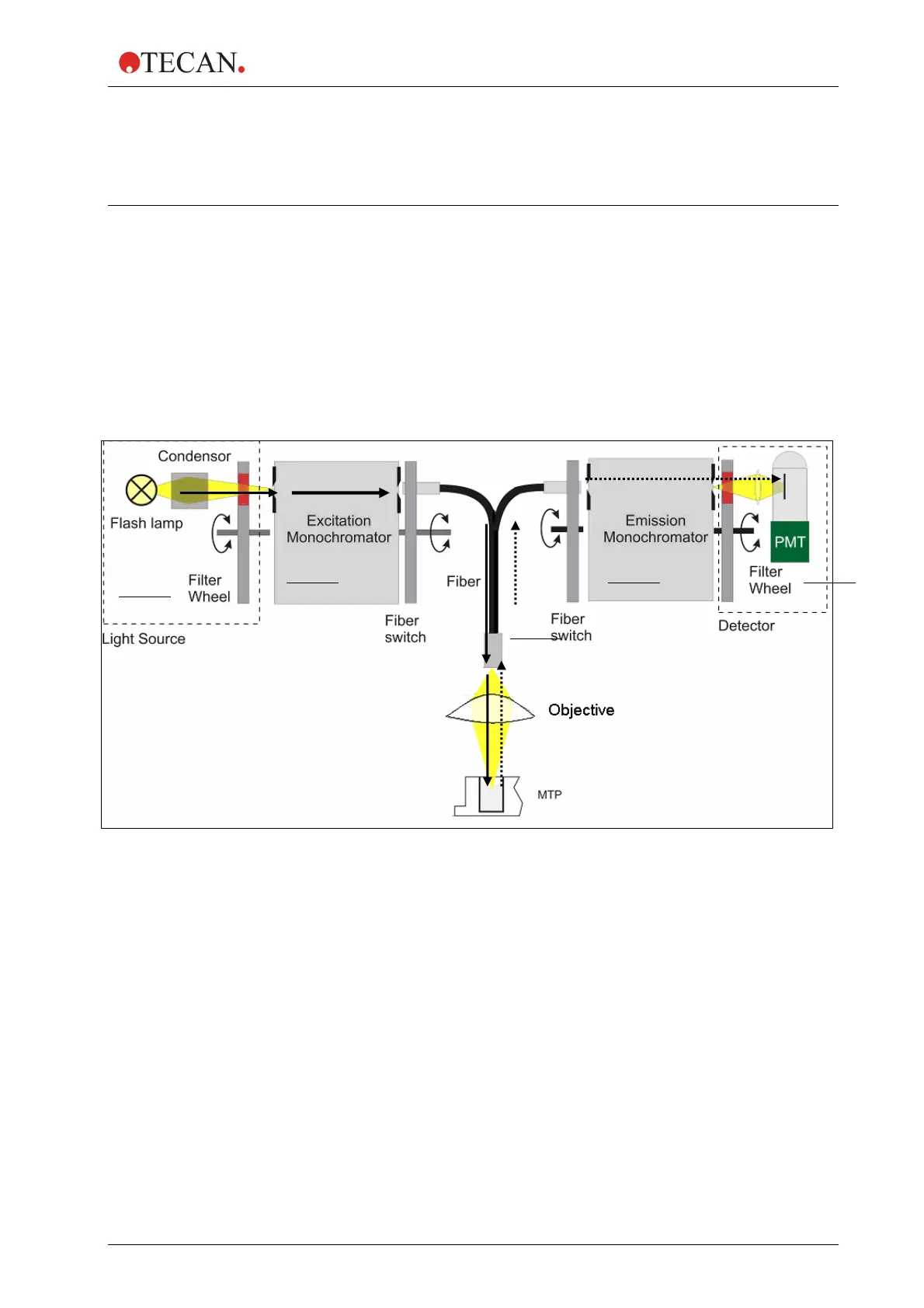
The optical system of the fluorescence top and bottom system of the
infinite
®
M200 is sketched below. The system consists of the light source system
(1) including the excitation double monochromator (2), the fluorescence top
optics (3), the emission double monochromator (4) and the fluorescence
detection (5). The solid arrows indicate the light path of the excitation light; the
dashed arrows indicate the emission light path. To simplify the system, the ‘Flash
Monitor’ (see 5.1.1; Flash Monitor) is not shown. Each monochromator unit,
(2) a
nd (4), is built of two gratings and a schematic view is displayed in more
detail in Figure 5-3.
Figure 5-1 O
ptical System Fluorescence Top
1
2
3
4 5