3. OPERATING PRINCIPLE AND COMPONENTS
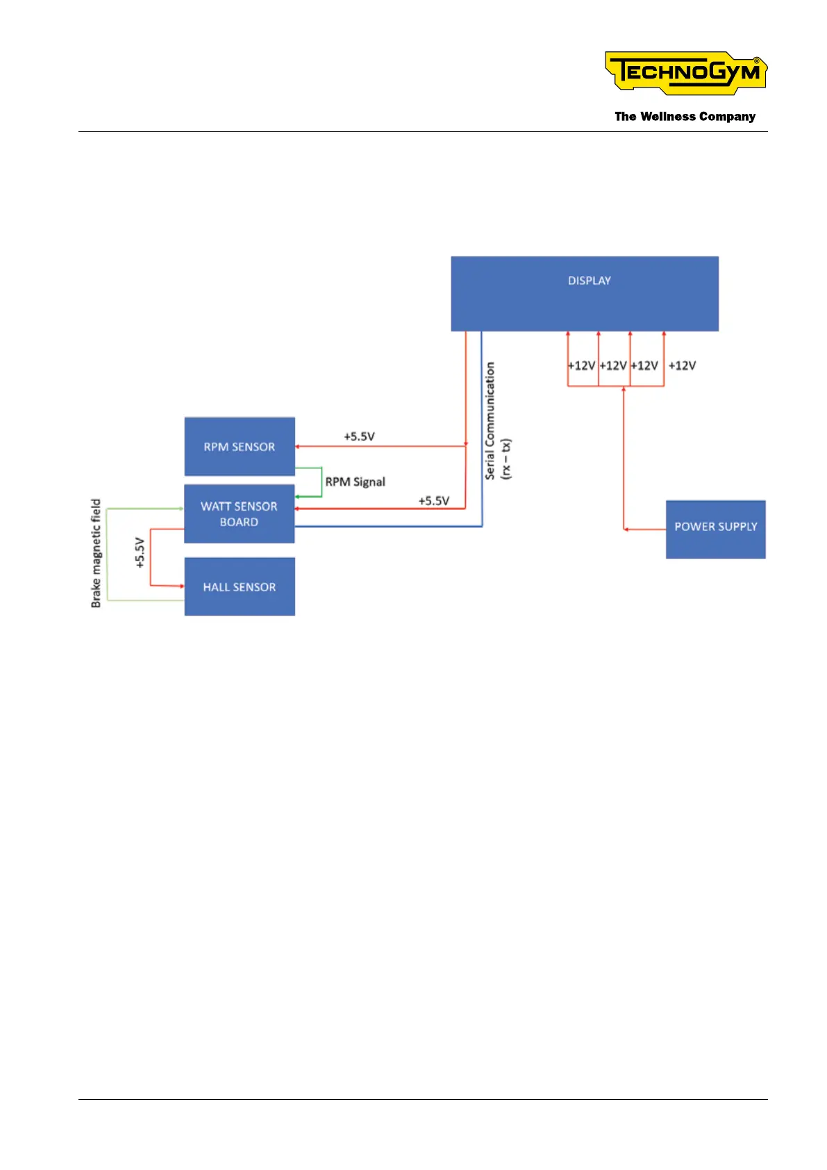
3.1 PRINCIPLE OF OPERATION SCHEME
Fig. 8
3.2 POWER SUPPLY
AC Input: 100-240V ~ 2.0A, 50-60Hz.
DC Output: 12Vdc 5A
3.3 HALL SENSOR
The Hall Sensor is xed to the device frame, as detailed in gure below. It acquires the braking
position based on the distance between the magnets and the brake and sends this information to
the Watt Sensor Board.
The Watt Sensor Board powers the Hall Sensor (+5.5V).
TECHNOGYM BIKE LIVE Technical Service Guide
Rev. 2.0
- 23 -TSG-00187-EN - Uncontrolled copy if printed