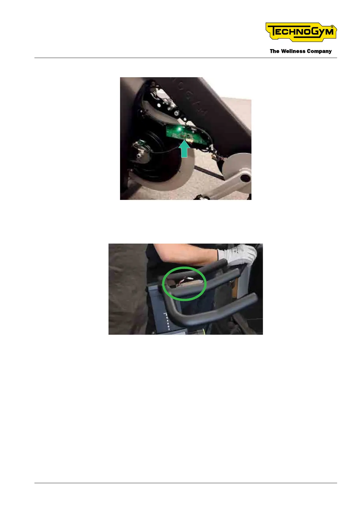
[1]: Watt Sensor Board powered (LED: Green):
Fig. 33
[2]: Check the presence of about 5Vdc between PIN 1 Red and PIN 2 Black of the Flying connector
2x2, accessible after removing the display group:
Fig. 34
[3]: Check the continuity of the RPM / Watt sensor cable 0WCU1068xx between:
_PIN 2 – White (of the Flying connector 3x2 pin) and PIN 4 - White (of the Watt Sensor Board con-
nector 6x1 pin).
_PIN 5 – Brown (of the Flying connector 3x2 pin) and PIN 3 – Brown (of the Watt Sensor Board
connector 6x1 pin).
[4]: Check the presence of about 5Vdc between PIN 29 yellow and Black wire of the Display con-
nector 20x2:
TECHNOGYM BIKE LIVE Technical Service Guide
Rev. 2.0
- 49 -TSG-00187-EN - Uncontrolled copy if printed