RUN XT: Service & Maintenance Manual - rev. 2.0
Page 6.24
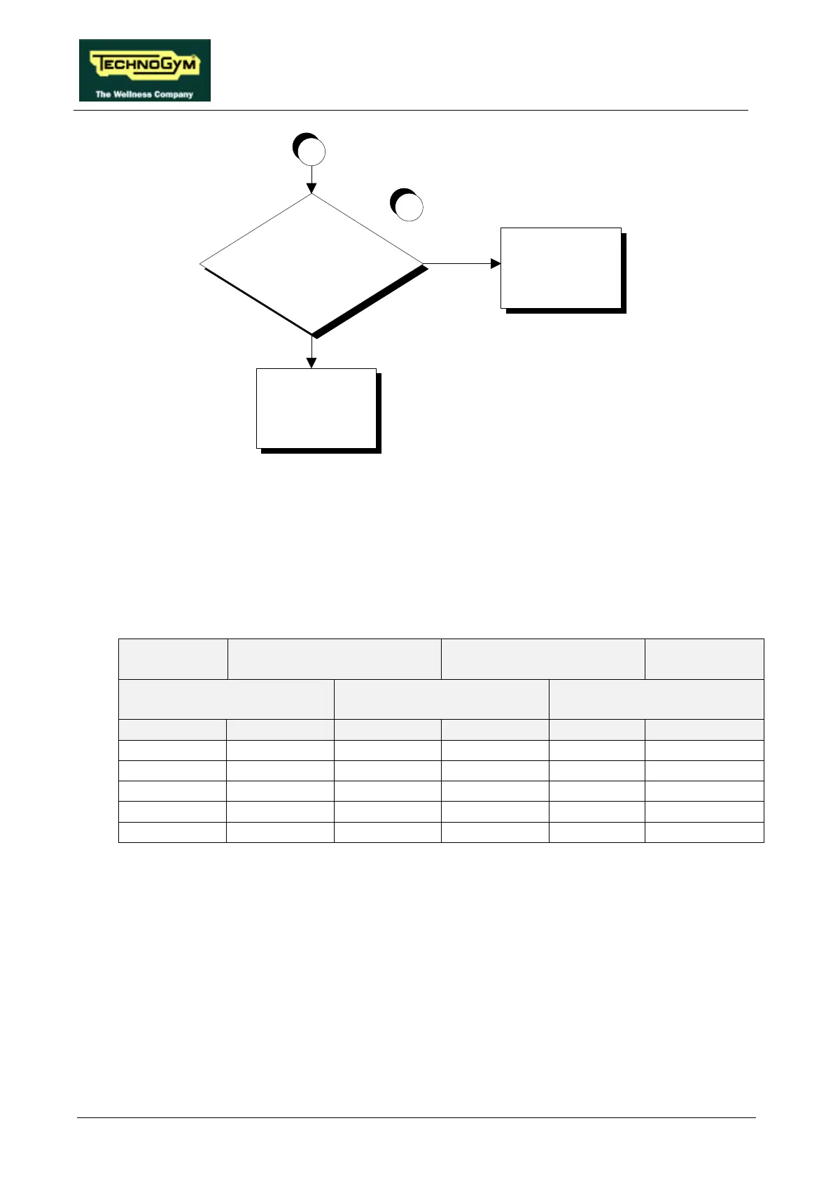
Is the inverter control PWM signal at
the output of the CPU board correct?
A
YES
Check and/or replace
cable RX-1 connecting
the CPU board and the
inverter interface board
Replace the CPU board:
see paragraph 7.3.
NO
6
Follow the procedure step by step to correctly diagnose the problem. Take particular care with the
checks highlighted by circled numbers, which are described in detail below:
(1) When the machine is in operation, check that the speed shown on the machine display and
inverter operating frequency correspond to the values shown in the tables below.
• For versions with speed expressed in km/h:
SPEED
(Km/h)
PWM SIGNAL
(Vdc)
ANALOG SIGNAL
(Vdc)
FREQUENCY
(Hz)
CPU BOARD INVERTER
INTERFACE BOARD
INVERTER
DISPLAY 6-3/CN1 10-3/CN2 5-6/CN1 L-0 DISPLAY
2.0 4.40 4.40 1.08 1.08 11.2
5.0 3.53 3.53 2.68 2.68 27.5
9.0 2.38 2.38 4.82 4.82 49.3
12.6 1.34 1.34 6.75 6.75 69.0
16.0 0.35 0.35 8.57 8.57 87.6
Table 6.6-1