RUN XT: Service & Maintenance Manual - rev. 2.0
Page 6.25
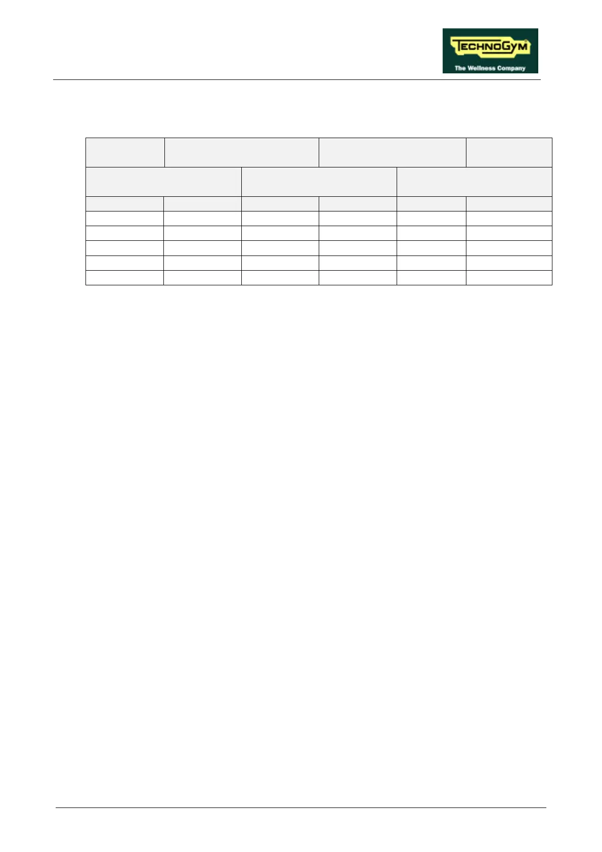
• For versions with the speed expressed in mph:
SPEED
(mph)
PWM SIGNAL
(Vdc)
ANALOG SIGNAL
(Vdc)
FREQUENCY
(Hz)
CPU BOARD INVERTER
INTERFACE BOARD
INVERTER
DISPLAY 6-3/CN1 10-3/CN2 5-6/CN1 L-0 DISPLAY
1.0 4.56 4.56 0.87 0.87 9.0
3.0 3.62 3.62 2.60 2.60 26.5
5.0 2.70 2.70 4.32 4.32 44.1
7.0 1.75 1.75 6.06 6.06 61.7
9.0 0.81 0.81 7.78 7.78 79.3
Table 6.6-2
Obviously, the voltages and frequencies quoted above are nominal values.
(2) Place the tester probes between the terminals 0 (signal) and L (ground) of the inverter. Check
that during machine operation the speed shown on the display and the voltage measured on the
inverter correspond to the values shown in Table 6.6-1 or in Table 6.6-2.
(3) See paragraph 9.4.
(4) Place the tester probes between pins 5 (signal) and 6 (ground) of connector CN1 on the
inverter interface board. Check that during machine operation the speed shown on the display
and the measured voltage correspond to the values shown in Table 6.6-1 or in Table 6.6-2.
(5) Place the tester probes between pins 10 (signal) and 3 (ground) of connector CN2 of the
inverter interface board. Check that during machine operation the speed shown on the display
and the measured voltage correspond to the values shown in Table 6.6-1 or Table 6.6-2.
(6) Place the tester probes between pins 6 (signal) and 3 (ground) of connector CN1 on the CPU
board. Check that during machine operation the speed shown on the display and the measured
voltage correspond to the values shown in Table 6.6-1 or in Table 6.6-2.