--
I
100
·
I
90
~
~\
'
ID
I
°(.
2mV
I
I\
j
11
'
I
\
\.
J \
·1
\
I
'
~J
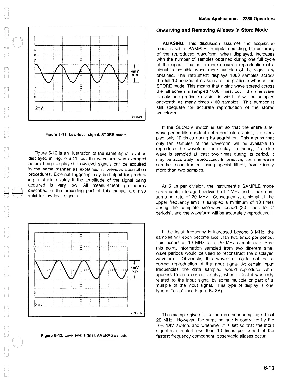
Figure 6-11. Low-level signal, STORE mode.
-.
4mV
P-P
_L
4998-24
Figure 6-12
is
an
illustration of the same signal level
as
displayed
in
Figure 6-11, but the waveform was averaged
before being displayed. Low-level signals
can
be
acquired
in
the same manner
as
explained
in
previous acquisition
procedures. External triggering may
be
helpful for produc-
ing a stable display if the amplitude of the signal
being
acquired
is
very low.
All
measurement procedures
described
in
the preceding part of this manual
are
also
valid for low-level signals.
f-
;
IO---l--+------+---+----+--f---+---l--+-------j
I
O'..·
2mV
Figure 6-12. Low-level signal, AVERAGE mode.
-•-
4998-25
Basic Applications-2230 Operators
Observing and Removing Aliases
in
Store Mode
ALIASING. This discussion assumes the acquisition
mode
is
set to SAMPLE.
In
digital sampling, the accuracy
of the reproduced waveform, when displayed, increases
with the number of samples obtained during
one
full
cycle
of the signal. That
is,
a more accurate reproduction of a
signal
is
possible when more samples of the signal are
obtained. The instrument displays 1000 samples across
the full
10
horizontal divisions of the graticule when
in
the
STORE mode. This means that a sine wave spread across
the full screen
is
sampled 1000 times, but if the
sine
wave
is
only one graticule division
in
width, it will
be
sampled
one-tenth
as
many times (100 samples). This number
is
still adequate for accurate reproduction of the stored
waveform.
If the SEC/DIV switch
is
set so that the entire sine-
wave period fills one-tenth of a graticule division, it
is
sam-
pled only 1 O times during its acquisition. This means that
only ten samples of the waveform will
be
available to
reproduce the waveform for display.
In
theory, if a sine
wave
is
sampled at least two times during its period, it
may
be
accurately reproduced.
In
practice, the
sine
wave
can
be
reconstructed, using special filters, from slightly
more than two samples.
At 5
µs
per division, the instrument's SAMPLE mode
has a useful storage bandwidth of 2 MHz
and
a maximum
sampling rate of
20
MHz. Consequently, a signal at the
upper frequency limit
is
sampled a minimum of
10
times
during the complete sine-wave period
(20
times for 2
periods),
and
the waveform will
be
accurately reproduced.
If the input frequency
is
increased beyond 8 MHz, the
samples will soon become less than two times per period.
This occurs at
10
MHz for a
20
MHz sample rate. Past
this point, information sampled from two different sine-
wave periods would
be
used to reconstruct the displayed
waveform. Obviously, this waveform could not
be
a
correct reproduction of the input signal. At certain input
frequencies the data sampled would reproduce what
appears to
be
a correct display, when
in
fact it was only
related to the input signal
by
some multiple or part of a
multiple of the input signal. This type of display
is
one
type of "alias"
(see
Figure 6-13A).
The
example given
is
for the maximum sampling rate of
20
MHz. However, the sampling rate
is
controlled by the
SEC/DIV switch,
and
whenever it
is
set
so
that the input
signal
is
sampled
less
than
10
times per period of the
fastest frequency component, observable aliases occur.
6-13

 Loading...


