--
GPIB Parameter Selection
The correct selection of GPIB parameters (primary
address, message terminator,
and
talk/listen
mode)
must
be
made
before power
on.
That
is
when the GPIB
PARAMETERS switch
is
read
to determine what the
address
and
other settings of the switch
are.
See
Table 7-6 (shown previously) to determine the specific
parameters switch settings.
PRIMARY ADDRESS-The selected GPIB address
establishes the talk
and
listen address for the oscilloscope.
It
can
be
set to
any
value
between O
and
31,
inclusive.
Address
31
is
"OFF LINE." With
an
address of
31,
the
instrument still presents
an
active load, but it neither
responds to nor interferes with
any
bus
traffic.
SECONDARY ADDRESS-Not implemented
in
the
2200 Family
of
digital storage oscilloscopes.
INPUT
END-OF-MESSAGE
TERM
I
NA
TOR-
The
end-
of-message terminator
can
be
selected to
be
either
the End-or-Identify
(EOI)
interface signal or the Line-Feed
(LF)
character.
When
EOI
(normal
mode)
is
selected
as
the terminator,
the instrument will:
• accept only
EOI
as
the end-of-message terminator,
and
• assert
EOI
concurrently with the last byte of
a message.
When
LF
is
selected
as
the terminator, the
instrument will:
• accept either
LF
or
EOI
as
the end-of-message termi-
nator,
and
•
send
Carriage Return
(CR)
followed
by
LF
at the
end
of every message, with
EOI
asserted concurrently
with
the
LF.
TALK/LISTEN
are
selectable:
MODE-Four
talk/listen
modes
• TALK
ONLY
mode
allows the instrument to
send
data over the
GPIB
but not to listen.
Options
and
Accessories-2230 Operators
• LISTEN ONLY mode permits the instrument to
receive data over the GPIB but not to talk.
• TALK/LISTEN mode (both
TON
and
LON
modes
unselected) allows the instrument to both
send
and
receive data over the GPIB.
•
OFF
BUS mode (both
TON
and
LON
modes selected)
switches the instrument off the
bus
(same
as
setting
address to
31).
To select a different Talk/Listen
mode,
see
the GPIB
PARAMETERS switch settings
in
Table
7-7.
The
new set-
tings must
be
made
before power
on
to
be
in
effect.
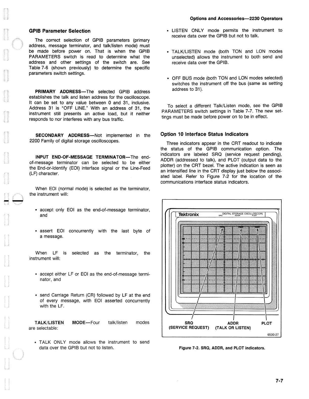
Option 10 Interface Status Indicators
Three indicators appear
in
the CRT readout to indicate
the status of the GPIB communication option.
The
indicators
are
labeled
SRO
(service request pending),
ADDA (addressed to talk),
and
PLOT (output data to the
plotter)
on
the CRT bezel.
The
active indication
is
seen
as
an
intensified
line
in
the CRT display just below the associ-
ated label. Refer to Figure
7-2
for the location of the
communications interface status indicators.
SRQ
ADDR
PLOT
(SERVICE REQUEST) (TALK
OR
LISTEN)
6530-27
Figure 7-2.
SRQ,
ADDR, and PLOT indicators.
7-7

 Loading...


