Options and
Accessories-2230
Operators
AUXILIARY Connector-Provides connections for
an
X-Y
Plotter
and
an
External Clock input (see Controls, Con-
nectors,
and
Indicators).
GPIB
Connector-Provides
the ANSI/IEEE Std 488-1978
compatible electrical and mechanical connection to the
GPIB. The connector is only
on
instruments with Option
10. The function
of
each pin
of
the connector is shown
in
Table 7-5.
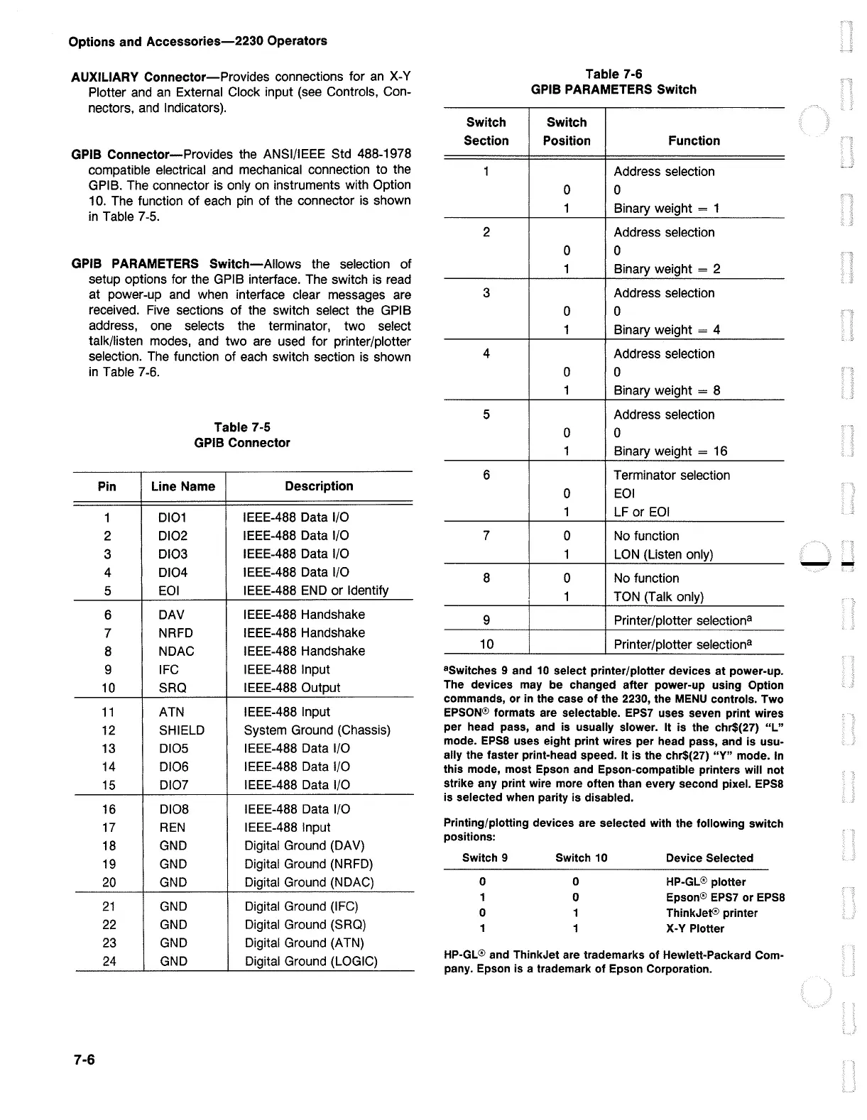
GPIB PARAMETERS
Switch-Allows
the selection
of
setup options for the GPIB interface. The switch is read
at power-up
and
when interface clear messages are
received.
Five
sections
of
the switch select the GPIB
address, one selects the terminator, two select
talk/listen modes, and two are used for printer/plotter
selection. The function
of
each switch section is shown
in
Table 7-6.
Pin
1
2
3
4
5
6
7
8
9
10
11
12
13
14
15
16
17
18
19
20
21
22
23
24
7-6
Table 7-5
GPIB Connector
Line Name
Description
0101
IEEE-488 Data 1/0
0102
IEEE-488 Data 1/0
0103
IEEE-488 Data 1/0
DIO4
IEEE-488 Data 1/0
EOI
IEEE-488
END
or Identify
DAV
IEEE-488 Handshake
NRFD IEEE-488 Handshake
NDAC
IEEE-488 Handshake
IFC
IEEE-488 Input
SRO
IEEE-488 Output
ATN IEEE-488 Input
SHIELD
System Ground (Chassis)
0105 IEEE-488 Data 1/0
DIO6 IEEE-488 Data 1/0
0107
IEEE-488 Data 1/0
0108 IEEE-488 Data 1/0
REN
IEEE-488 Input
GND
Digital Ground (DAV)
GND
Digital Ground (NRFD)
GND
Digital Ground (NDAC)
GND
Digital Ground (IFC)
GND
Digital Ground (SRQ)
GND
Digital Ground (A TN)
GND
Digital Ground (LOGIC)
Table 7-6
GPIB PARAMETERS Switch
Switch Switch
Section Position Function
1 Address selection
0 0
1 Binary weight = 1
2 Address selection
0 0
1 Binary weight = 2
3 Address selection
0 0
1 Binary weight = 4
4 Address selection
0 0
1
Binary weight = 8
5 Address selection
0 0
1 Binary weight = 16
6 Terminator selection
0
EOI
1
LF or
EOI
7
0 No function
1
LON
(Listen only)
8 0 No function
1 TON (Talk only)
9 Printer/plotter selectiona
10 Printer/plotter selectiona
8
Switches 9 and
10
select printer/plotter devices at power-up.
The devices
may
be changed after power-up using Option
commands,
or
in
the case
of
the 2230, the
MENU
controls. Two
EPSON@
formats are selectable. EPS7 uses seven print wires
per head pass,
and
is
usually slower. It
is
the chr$(27) "L"
mode.
EPSS
uses eight print wires per head pass, and
is
usu-
ally the faster print-head speed. It
is
the chr$(27) "Y" mode.
In
this mode, most Epson and Epson-compatible printers
will
not
strike any print wire more often than every second pixel.
EPSS
is
selected when parity
is
disabled.
Printing/plotting devices are selected
with
the following switch
positions:
Switch 9 Switch
10
Device Selected
0 0
HP-GL@
plotter
1
0
Epson@
EPS7
or
EPSS
0 1
ThinkJet® printer
1
1
X-Y Plotter
HP-GL®
and ThinkJet are trademarks
of
Hewlett-Packard Com-
pany. Epson is a trademark
of
Epson Corporation.
--

 Loading...


