Analyzing Wavef
orms
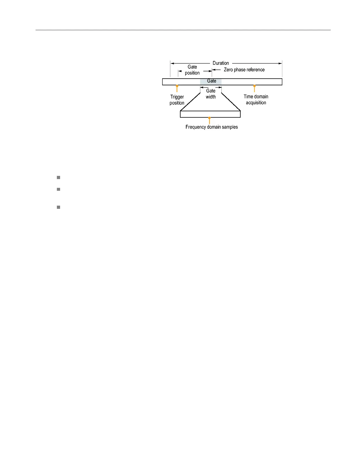
Using the Gating Controls
Gating determines which portion of the
acquired waveform is transformed into the
frequency domain. The gate has a position
and a width control. The gate position is the
time in seconds from the trigger location to
the center 50% position of the gate interval.
The position and width units are seconds.
Using the Frequency Controls
The frequency domain controls for the spectral waveform are:
Span, which is the frequency at the end of the spectral waveform minus the frequency at the beginning of the waveform.
Center, which is the frequency at the center of the spectral waveform. Center is equal to the start frequency plus
one half of the span.
Resolution bandwidth, which is the 3 dB down bandwidth of the spectral analyzer frequency response to a sine wave
input.
Using the Magnitude Con trols
Vertical units can b e either linear or log. When the spectrum is linear magnitude, the vertical units are the same as the source
waveform. W hen the vertical s cale of the magnitude spectrum is set to dB, use the Reference Level Offset to set which
vertical position in the magnitude spectrum is zero dB. Setting the vertical scale to dBm sets the Reference Level Offset
to a value that is equivalent to 1 mW of power into 50 Ω.
The value of the Reference Level is the magnitude at the top of the display screen. Reference Level does not change the
spectral data but Reference Level Offset does. Adjusting the R eference Level Offset causes the spectral waveform to move
vertically with respect to the waveform reference marker. This moves the waveform without changing the Reference
Level control setting.
Using the Phase Controls
You can set the vertical units to Degrees, Radians, or Group Delay in seconds. Phase is a relative measurement that must
have a time domain reference point. The phase value is specifi ed with respect to this phase reference position.
The spectral analyzer produces phase values from -p to p radians or -180 to 180 degrees. However, when you perform
impulse response testing and the phase is continuous, then phase values outside these ranges may occur. The spectral
analyzer then wraps the data with discontinuities in the display from +180 to -180 degrees. Phase unwrap will display the
correct result by unwrapping the phase. Phase unwrap is only valid when the phase spectrum is a continuous function of
frequency. Therefore, do not use it when analyzing the harmonic c ontent of the typical repetitive signal.
Random noise in the spectrum may have phase values over the entire range. This could make the phase display unusable.
However, you can set the suppression threshold control to a level in dB . The phase of any complex spectral points with a
magnitude below this threshold is set to zero.
TDS6000B & TDS6000C Series Quick Start User Manual 59
 Loading...
