6-13
Troubleshooting
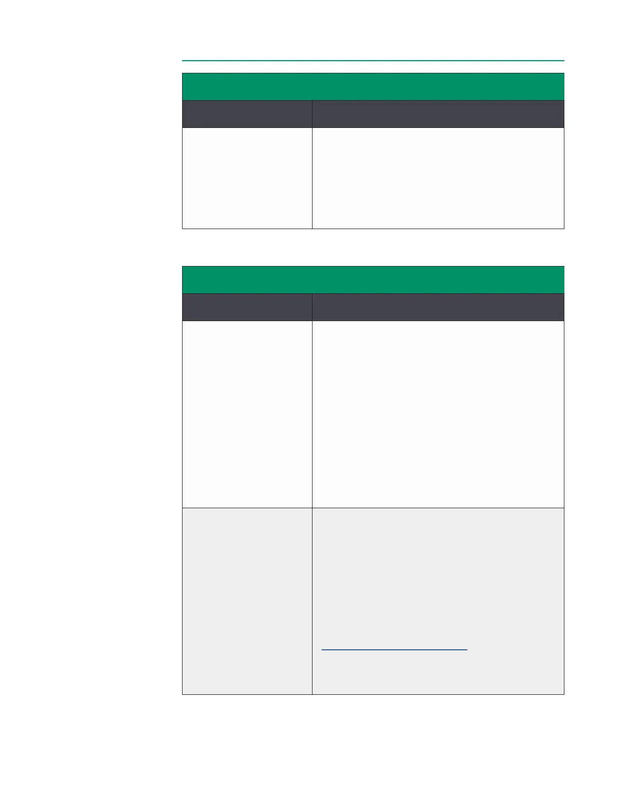
FLOW INTERFACE MODULE AND SENSORFLOW INTERFACE MODULE AND SENSOR
MessageMessage Meaning and Corrective ActionMeaning and Corrective Action
(Name)
Flow Module-[SN]
Sensor change
F203
The system detected a change to the Flow Sensor
size connected to a Flow Interface Module while in
Measurement Mode.
Conrm alarm limits are appropriate for the sensor.
Conrm the Flow Sensor color identier matches
the conguration.
HLM INTERFACE MODULEHLM INTERFACE MODULE
MessageMessage Meaning and Corrective ActionMeaning and Corrective Action
HLM Interface
Module-[SN] failure
P001
P004
P006
P007
P008
P010
P011
P012
P013
P014
P055
P056
A problem was detected in the HLM Interface
Module electronics.
It may be possible to reset the HLM Interface
Module by disconnecting and reconnecting it to
the Core. If the issue persists, use a replacement
HLM Interface Module and contact Terumo
Cardiovascular Technical Support.
Check HLM Interface
Module-[SN] connection
P050
P051
P052
P053
P054
P301
Data is invalid or is not being received from the
source HLM/pump device while in Measurement
Mode.
Conrm the correct HLM is selected in the case
prole. Check connections between the Core and
the Interface Module and between the Interface
Module and pump. Check the serial cable to ensure
it is the right interface cable for that HLM.
Ensure the HLM is congured per the instructions in
Chapter 3, “Sensor Connections.” Try a replacement
serial cable and/or Interface Module. If the issue
persists, contact Terumo Cardiovascular Technical
Support.