1-12
System Overview
CoreCore
The CDI Core provides power to all connected modules and module-to-module
communication, such as between the Calibrator and the BPM. Any calculated parameter
that requires input from more than one module is calculated in the Core and sent to
the Display. The Core has a 25-minute battery backup for use during transport or for
emergency power.
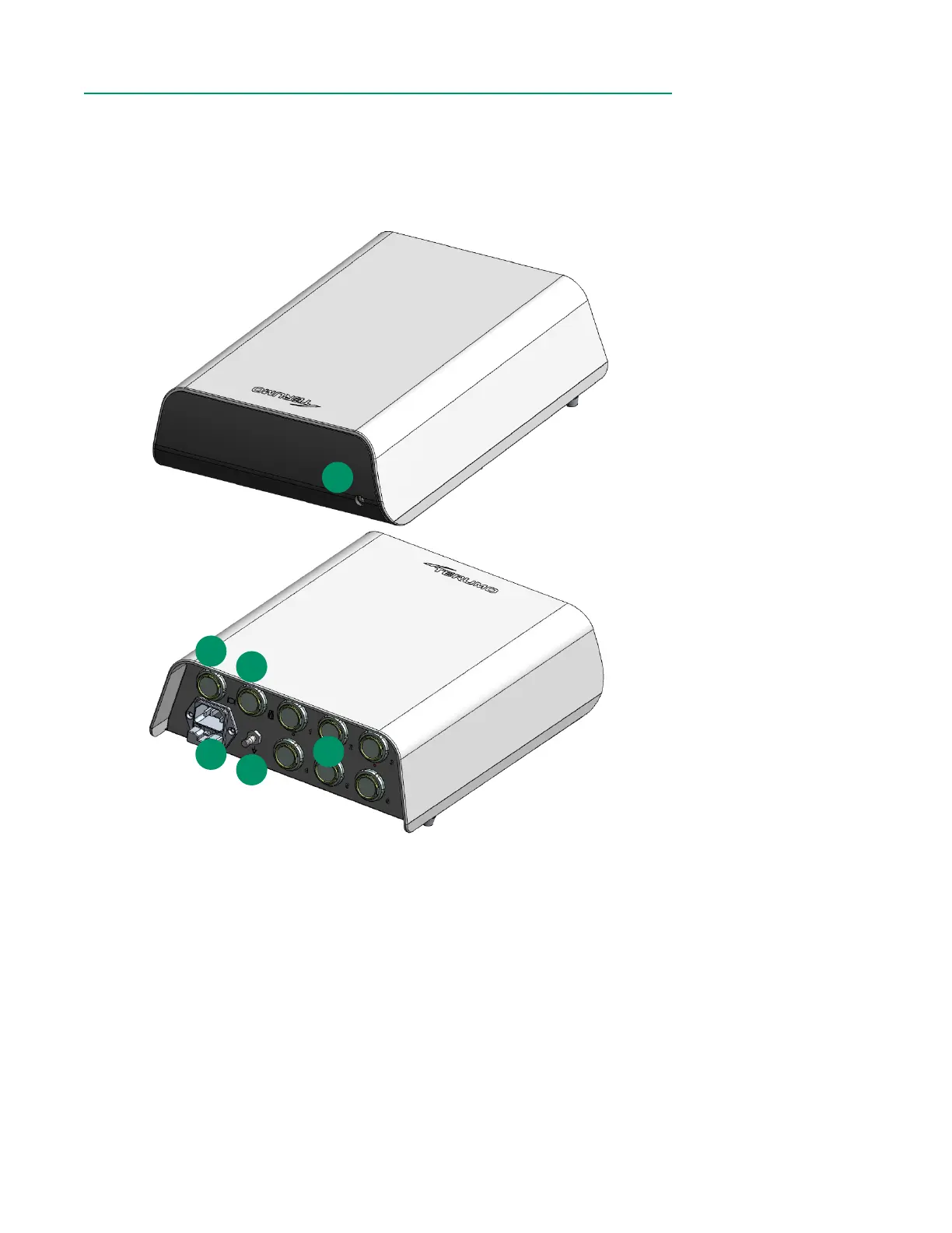
1. LED status indicator light: Indicates functional status. The LED is steady white
when the system is off and power is connected. The LED ashes green while
the system is starting up. The LED is steady green when the system is ready for
use. The LED ashes white while the system is shutting down.
2. Display port: Interfaces with the CDI Model CDI751 OneView Touchscreen
Display
3. Calibrator port: Interfaces with the CDI Model CDI740 Calibrator.
4. Module ports x 6: Attaches BPM(s), H/S(s), Flow Interface Module(s) and
External Device Module(s).
5. Power connector: Connects the power cable.
6. Ground equalization stud: Used to reduce differences of electrical potential
between bodies of medical electrical devices and conductive parts of other
objects.
1
5
6
Front
4
2
Back
3