4-3
Calibration and Circuit Setup
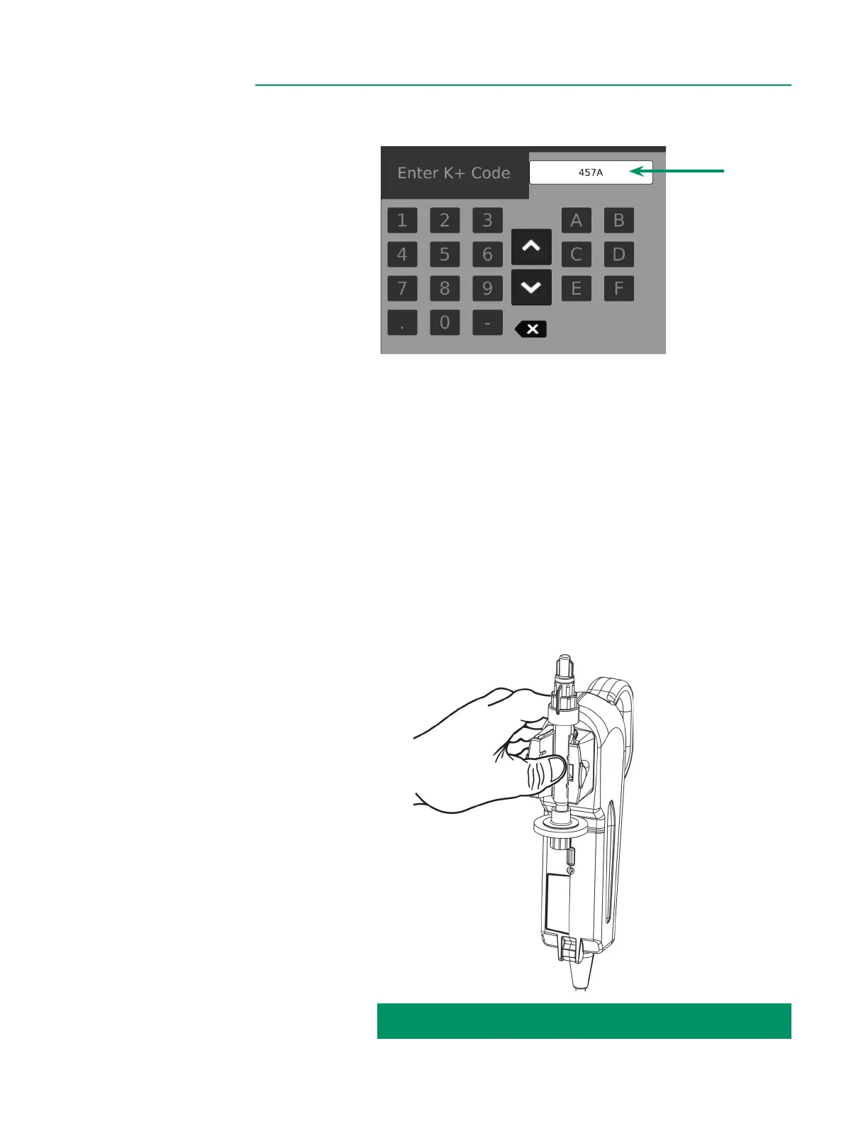
3. The K
+
Code is a three-digit number and letter listed on the label of the Shunt
Sensor’s foil pouch. Tap the entry eld on screen and input the K
+
Code.
Optional: For Shunt Sensor packaging that includes a 2D barcode, the K Code
can be entered by scanning using the camera under the Display.
Tap the barcode icon and align the barcode under the Display until the barcode
is captured and shown on screen.
4. Ensure the K
+
Code entered matches what is shown on the package.
5. Verify Shunt Sensor expiration date(s).
Note: The barcode camera also veries expiration dates.
6. Remove BPM from the holder on the back of the Display.
7. Attach the Shunt Sensor to the BPM by aligning it with the BPM optical head.
Press rmly in the center of the Shunt Sensor (between the wings) until the
Shunt Sensor snaps into place to create the BPM assembly.
Note: The sensor will snap securely onto the BPM and will t only one way.
CALIBRATION INSTRUCTIONS CONTINUED ON NEXT PAGE: