4-8
Calibration and Circuit Setup
Conclude CalibrationConclude Calibration
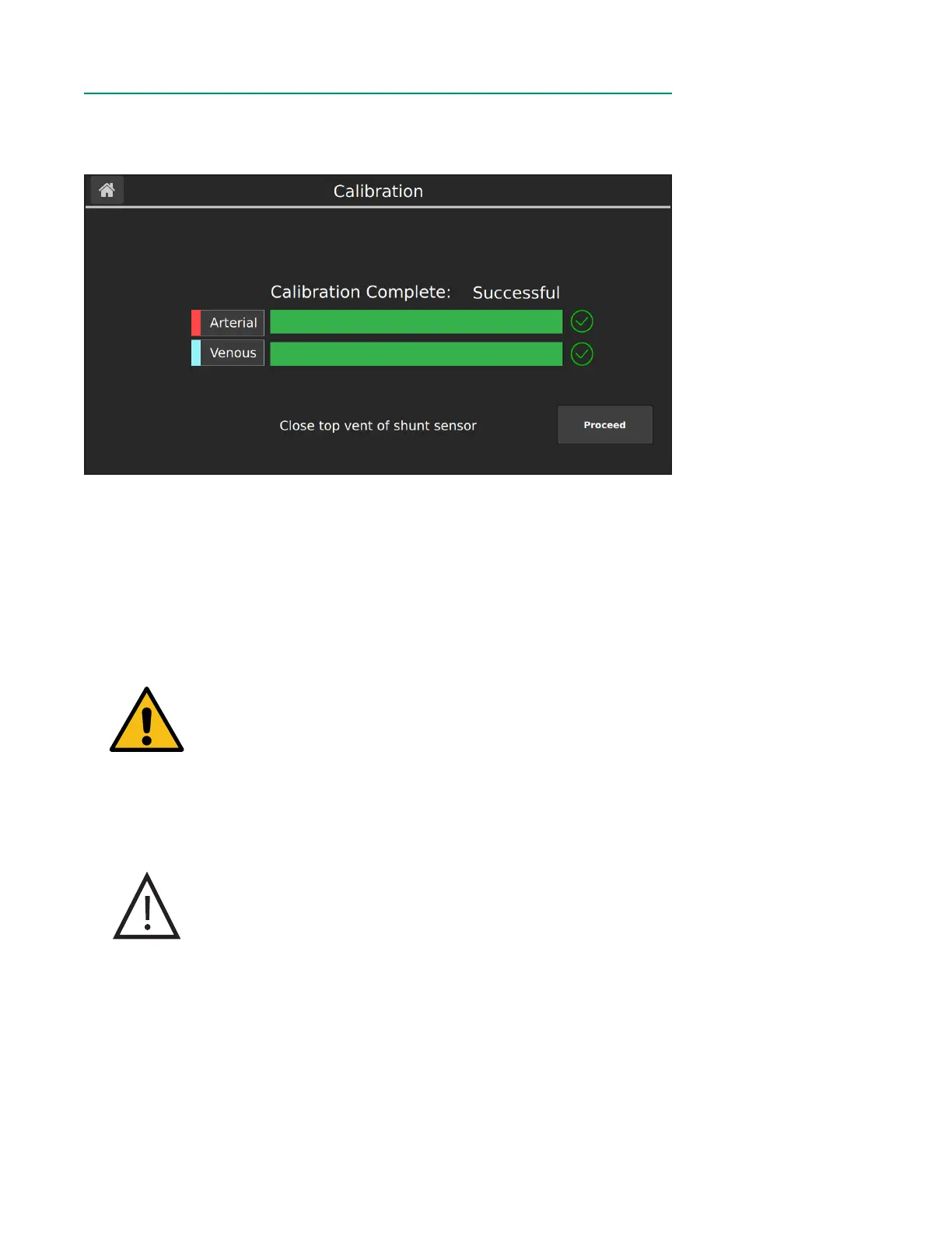
After the calibration is successfully completed, the following window appears.
Follow the steps below to conclude calibration:
1. Verify that the calibration was successful by ensuring no error messages have
appeared on screen and that a green checkmark is displayed next to both
sensors.
2. (Optional) Disconnect the calibrator cable from the Calibrator.
3. Using sterile technique, close the top vent on the Shunt Sensor(s).
4. Tap Proceed.
Warning
Make sure the top vent of each Shunt Sensor is tightened
securely to avoid leakage and maintain sterility.
5. Remove the BPM assembly(s) from the calibrator. If you are not placing the
sensor in-line within one hour of gas calibration, re-attach the bottom blue
Luer cap to the lter/sparger assembly.
Caution
Do not use the cable connected to the BPM to pull the BPM
assembly out of the calibrator. Pulling on the cable may result
in wire damage.
6. To place the BPM(s) on the BPM bracket(s), align the T-shaped slot of the BPM
to the T-shaped bar of bracket plate and slide into place.
Notes: After calibration, as long as buffer solution level is above the top microsensor
and all caps are tightly fastened, the sensors can be used for up to 24 hours.