Configuring the Receiver Using PC-CDU
P/N 7010-1004
3-39
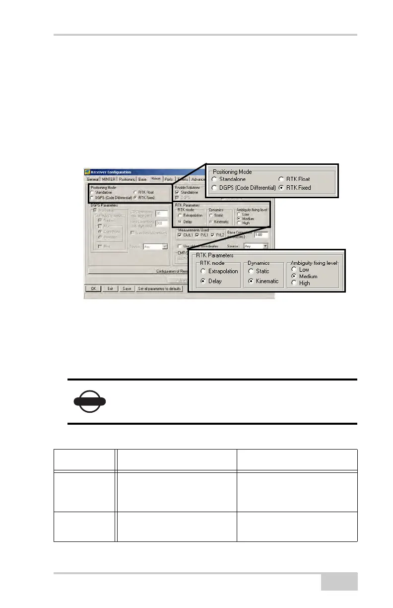
• RTK Parameters, Dynamics – select Static or Kinematic.
RTK Parameters, Ambiguity fixing level – (not applicable to
RTK Float) select either Low, Medium, or High for indicator
states of 95%, 99.5%, or 99.9%, respectively. The RTK
engine uses the ambiguity fix indicator when making
decisions whether or not to fix ambiguities. The higher the
specified confidence level, the longer the integer ambiguity
search time.
Figure 3-36. Rover Configuration
Continue with step 11 for RTK surveys or step 12 on page 3-39.
11. For RTK surveys, click the Ports tab and set the following port
parameters for the serial port (Table 3-4), then click Apply
(Figure 3-36 on page 3-39).
For post-processed surveys, keep the default values
for these parameters.
Table 3-4. Receiver Parameters for the Ports Tab
Parameter Base Receiver Rover Receiver
Input n/a (Leave the default.) Select the same differential
correction format selected for
the Base.
Output Select the type and format of
differential corrections.
Select “None”.