1-9
1 NOMENCLATURE AND FUNCTIONS
●
Screen two
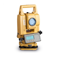
6.Electric circular level graphic display
Electric circular level can be displayed by graphic. This function is good for level the instrument
when the circular level is difficult to see directly.
Press the [F6] key to get to Screen 2 on the display.
Press the [F1] key to display the graphic.
In the displays of reverse side, the graphic bubble moves in reverse.
7.Set audio mode
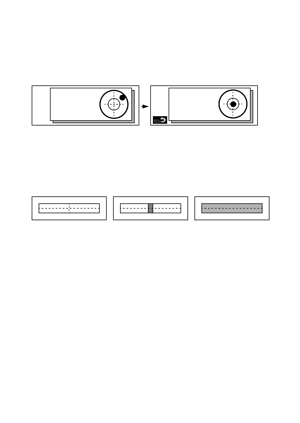
The light acceptance quantity level (Signal level) is displayed in this mode.
When reflected light from the prism is received, a buzzer sounds. This function is good for easy
collimation when the target is difficult to find.
Press the [F6] key to get to Screen 2 on the display then press the [F2] key on screen 2.
The received return signal level is displayed with bar graph as follows.
(1) To stop the buzzer, refer to Chapter 7-PARAMETERS SETTING MODE.
(2) Also, it is possible to display the signal level in Distance Measuring Mode.
8.Setting Temperature, Pressure, Atmospheric correction value (PPM), Prism constant value
(PSM)
Press the [F6] key to get to Screen 2 on the display then press the [F3] key on screen 2.
The temperature, pressure, PPM, and PSM can be viewed.
Refer to Chapter 9-SETTING THE PRISM CONSTANT VALUE and Chapter 10-SETTING
ATMOSPHERIC CORRECTION, for further instructions.
9.Point guide ( Only for Point guide type)
This feature is most useful when doing stake out work. The Point Guide's red LEDs on the GTS-600
Series telescope assist the rod person in getting on-line. The Point Guide feature is fast and simple
to use.
•
Operating Instructions
Press the [F6] key to get to Screen 2 on the display then press the [F4] key to turn ON the Point
Guide LEDs. The Point guide icon on the display will become bright when turned ON. Looking the
objective lens of the telescope, the right LED will blink and the left LED will stay lit.
Rotate the leveling screws while observing the display.
After leveling, press [F1]. The display changes to the previous mode.
X:
Y:
X:00°00'00"
Y:00°00'00"
Maximum quantity level
Minimum quantity levelNo light acceptance