Configuring the Receiver
P/N 7010-0526
3-21
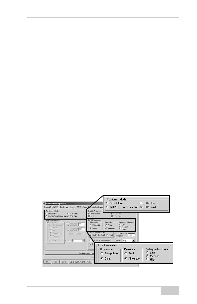
10. For the Rover receiver, click the Rover tab and set the following
parameters, then click Apply (Figure 3-21).
• Positioning Mode – For post-processed surveys, select
Standalone; for RTK surveys, select RTK float or RTK fixed.
• RTK Parameters, RTK mode – select either Extrapolation for
RTK float (kinematic) or Delay for RTK fixed (static).
– Extrapolation is for low-latency, high frequency output
(>= 5 Hz) RTK applications. The Rover will extrapolate
the Base station’s carrier phase measurement corrections
when computing the Rover's current RTK position.
– Delay is for 1 Hz high precision RTK applications. The
Rover RTK engine will compute either a delayed RTK
position (for the epoch to which the newly received
RTCM/CMR message corresponds) or the current stand-
alone position (while waiting for new RTCM/CMR
messages coming from the base).
• RTK Parameters, Dynamics – select Static or Kinematic.
• RTK Parameters, Ambiguity fixing level – (not applicable to
RTK Float) select either Low, Medium, or High for indicator
states of 95%, 99.5%, or 99.9%, respectively. The RTK
engine uses the ambiguity fix indicator when making
decisions whether or not to fix ambiguities. The higher the
specified confidence level, the longer the integer ambiguity
search time.
Figure 3-21. Rover Configuration