LS‐B10WLaserReceiverSetup
42
X‐63/X ‐63i/X‐62/X‐33/X‐32Installationand Calibra tion Manual P/N:7010‐0697
LS-B10W Laser Receiver Setup
TheLS‐B10WLaserReceiveraddsalaserheightreferencetothe2Dexcavatorsystem.TheLS‐B10Wis
calibratedforitslocationonthestickoftheexcavator.ItisnotavailableforX‐32systems.
LS-B10W Mounting
TheLS‐B10WLaserReceiverandbracketmustbemountedontheleftsideofthestick.Thefollowingsection
describesbracketmounting,cablerouting,andLS‐B10WLaserReceivermounting.
1. BeforeinstallingtheLS‐B10Wbracket,youmustassemblethebracketkit;seetheLS‐B10WIndexing
BracketAssemblyInstructions(p/n:7030‐1370)formoreinformation.
2. Afterassemblingthebracket,cleanthepaintedsurfaceofthemachine’sstickintheareawherethe
bracketwillbemounted.Removethebackingfromthedouble‐sidedtapeandmountthebracket
ontothestickorientationasshowninFigure58onpage43.
3. InstalltheLS‐B10Wontothebracket.
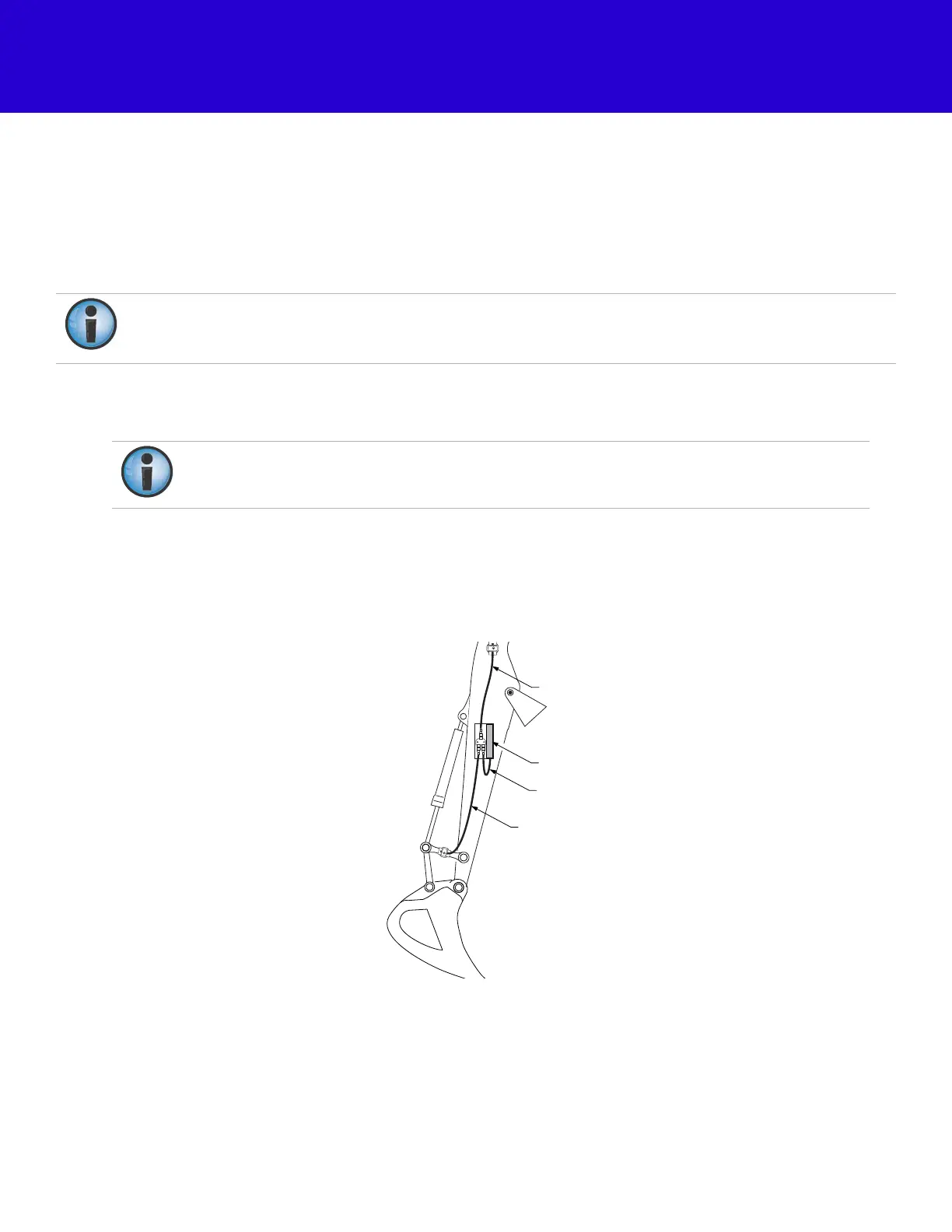
4. RoutethecablesasshowninFigure57.
Figure57:LS‐B10WCableRouting
Amarkonthelaserreceiverandthecrosshairsonthemountingbracketareusedtodetermineits
positiononthestick.Theorientationisselectedinthe
LaserReceiver(LSB10W)Calibration
screenin3D‐
MC.
Whendeterminingmountinglocation,becautiousoflimitationsincablelengths.
LS-B10W Laser Receiver
LS-B10W Cable
Bucket Sensor Cable
Stick Sensor Cable