Verifying Setup
54
X‐63/X‐63i/X‐62/X‐33/X‐32InstallationandCalibrationManual P/N:7010‐0697
Method B: Measuring to a hub at 180°
Beforeyoubegin,ensurethatallequipmentandmeasurementsareusingthesameunitsofmeasure(i.e.
Meters,SurveyF eet,etc.).
RecordMeasurements:
1. Positionthemachineonaflatandstablesurface,andplaceahubinaflatopenarea.
2. Using3D‐MCasareference(inalocalizedproject),taptheElevationControlKey,theleftGPS
info...button,andthentapthePositiontab.
3. Positionthemachinedirectlynorth.Bothbucketedgeswill havethesameNorthingvalue
(Figure72onpage52).
4. Extendthemachineelementstotheirfullestreach,andloweronebucketcornertothehub.
5. RecordtheNorthingvalueofoneofthebucketcorners(e.gNorthing
N
=4720.25).
6. Raiseonlytheboom,movethemachineforwardbeyondthehub,androtatethemachinebody
180°tofacedirectlysouth.
7. Usingthesamebucketcornerchoseninstep5,placethecorneronthehubandrecordthe
Northingvalue(e.g.Northing
S
=4720.45).
8. CalculatethedifferenceinNorthingvalues(e.g.Northing
DIFF
=Northing
N
‐Northing
S
=‐0.20).
CalculateAdjustments:
Usethefollowingequationtodeterminetherequiredadjustment:
Adjustment=[Northing
DIFF
/2](seeTable5).
1. Adjustthevaluein3D‐MCforboththeMainandAuxantennasbythecalculatedamount.
2. RepeatallstepsofMethodBtoverifythecorrection.
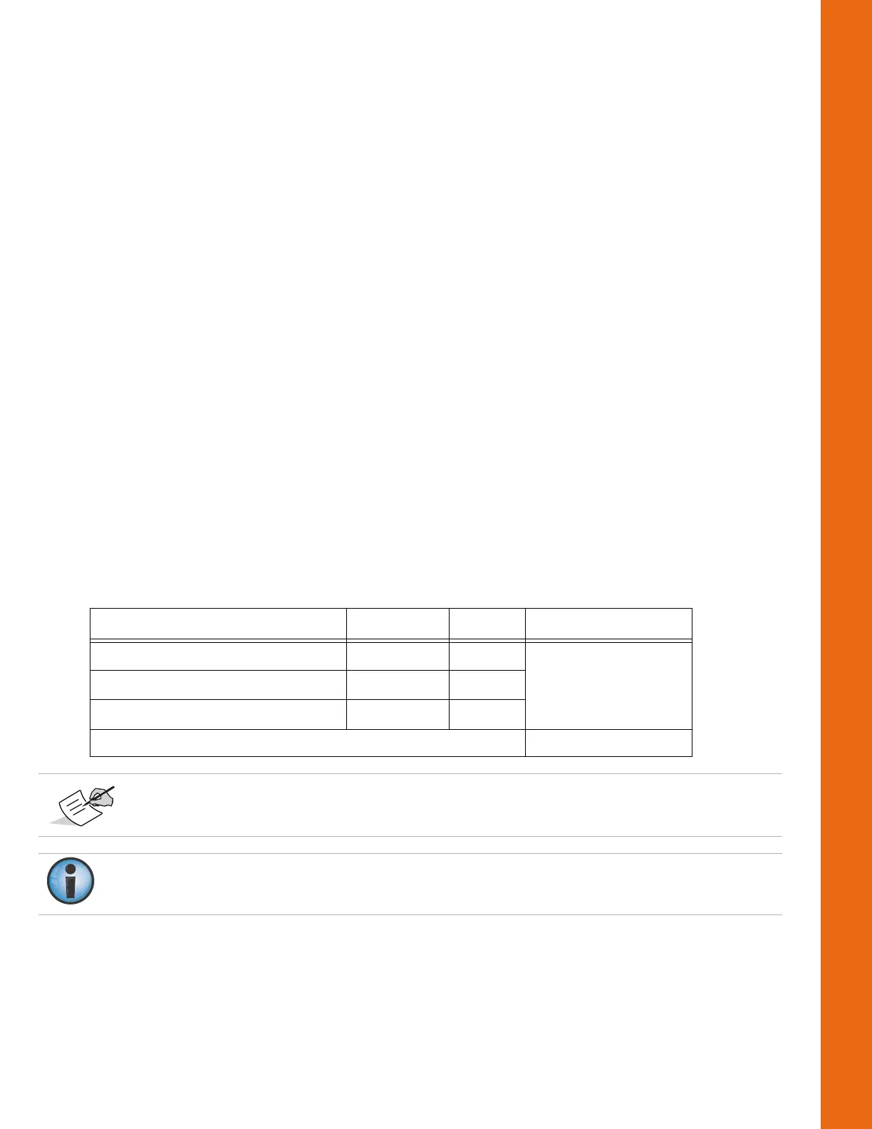
Table5.MeasureExtendedPositionsExampleCalculation
Measurement Symbol Value Adjustment
HubNorthing(F acingNorth) Northing
N
4720.25
HubNorthing(F acingSouth) Northing
S
4725.45
NorthingDifference Northing
DIFF
‐0.20
[‐0.20/2]=‐0.10
Positiveadjustmentsshouldbe addedtothe3D‐MCvalues,andnegativeadjustments
shouldbesubtracted.
FailuretoadjusttheAuxAntennavaluewillresultinarotationalerror.Donotphysically move
theantenna.
 Loading...