Verifying Setup
53
X‐63/X‐63i/X‐62/X‐33/X‐32InstallationandCalibrationManual P/N:7010‐0697
CalculateAdjustments:
1. Usethefollowingequationtodeterminetherequiredadjustment:
Adjustment=[(Measured
TAPE
‐Northing
DIFF
)/2](seeTable4).
2. Adjustthevaluein3D‐MCforboththeMainandAuxantennasbythe
calculatedamount.
3. RepeatallstepsofMethodAtoverifythecorrection.
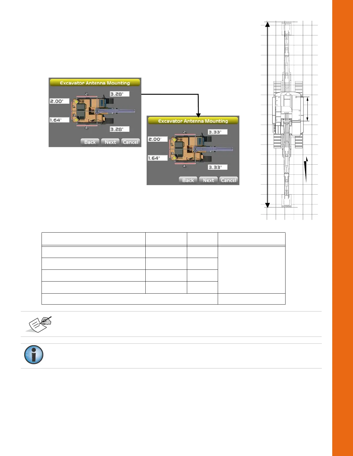
Figure73:AdjustMainAntennaonBody
Table4.MeasureExtendedPositionsExampleCalculation
Measurement Symbol Value Adjustment
Northing(FacingNorth) Northing
N
4740.72
Northing(FacingSouth) Northing
S
4695.22
NorthingDifference Northing
DIFF
45.50
MeasuredDistanceBetweenMarks Measured
TAPE
45.30
[(45.50‐45.30)/2]=‐0.10
Two Machine Positions over Two Points
Positiveadjustmentsshouldbe addedtothe3D‐MCvalues,andnegativeadjustments
shouldbesubtracted.
FailuretoadjusttheAuxAntennavaluewillresultinarotationalerror.Donotphysicallymove
theantenna.