Verifying Setup
61
X‐63/X‐63i/X‐62/X‐33/X‐32InstallationandCalibrationManual P/N:7010‐0697
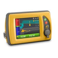
3. Toavoidrotationalerrors,adjustthe3D‐MCvaluesoftheAuxAntenna
tomatchthoseoftheMainAntennainthesamedirection.
•
ApositiveadjustmentmadefortheMainAntennashouldbesubtracted
fromthe3D‐MCvaluesoftheAuxAntenna(thedistanceawayfromthe
centerlinedecreases).
•
AnegativeadjustmentmadefortheMainAntennashouldbeaddedto
the3D‐MCvaluesoftheAuxAntenna(thedistancefromthecenterline
increases.
4. RepeatallstepsofMethodBtoverifythecorrection.
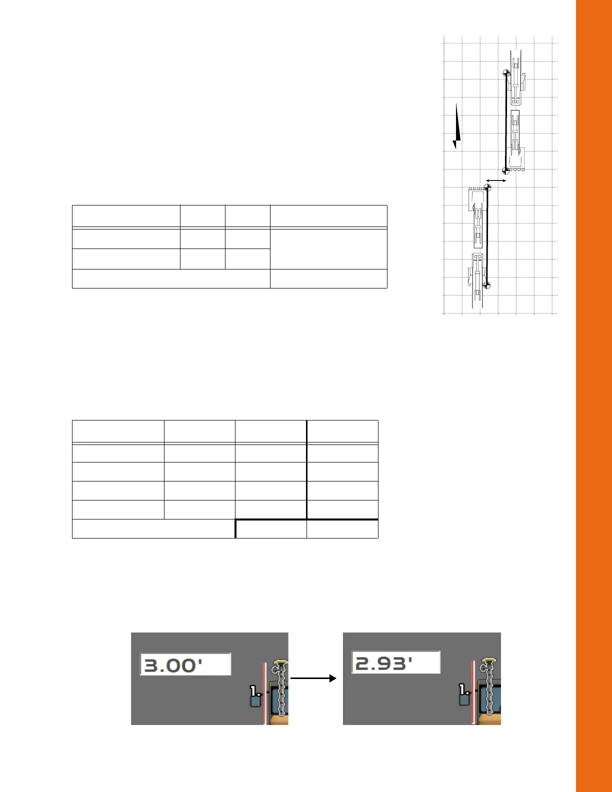
Verifying Main Antenna Height
Thedistancefromthemainantennatotheboompivotaffectstheoverallelevation3D‐MCcalculatesfor
thebucket.Ifthereisanoverallbias,themainantennaheightcanbeadjusted.
Recordseveral3D‐MCbucketelevationsandcorrespondingsurveyroverelevations.Subtractthe
elevationsandfindtheaverage.
Donotphysicallyadjusttheantennaheight.
•
Ifthereportedaverageelevationsof3D‐MCarehigherthanasurveyrover,increasetheantenna
heightvaluein3D‐MC.
•
Ifthereportedaverageelevationsof3D‐MCarelowerthanasurveyrover,decreasetheantenna
heightvaluein3D‐MC(Figure75).
Figure75:AdjustMainAntennaHeight
Table9.ExampleCalculationswithoutaSurveyRover
Measurement Symbol Value Adjustment
HubEasting(FacingN) Easting
N
520.35
HubEasting(FacingS) Easting
S
520.41
[(520.41‐520.35)/2]=0.03
Table10.MeasureLocationsandDetermineDifference
Elevations 3D‐MC Rover Difference
Location1 101.10 101.17 ‐0.07
Location2 120.30 120.36 ‐0.06
Location3 99.50 99.58 ‐0.08
Location4 114.20 114.26 ‐0.06
Average ‐0.07
N
Extended
0.06
Curled In
Curled In
 Loading...