Verifying Setup
58
X‐63/X‐63i/X‐62/X‐33/X‐32InstallationandCalibrationManual P/N:7010‐0697
CalculateAdjustments:
1. Calculatetheadjustmentneededin3D‐MCforAuxAntenna‐to‐Boomlengthusingthefollowing
equation:
Adjustment=[Easting
Diff
/Ratio
Dist
](seeTable7).
2. Adjustthevaluein3D‐MCfortheAuxAntennabythecalculatedamount.Donotphysicallymove
theantenna.
3. RepeatallstepsofMethodBtoverifythecorrection.
Verifying Antenna-to-Boom Centerline Length
ThisprocessissimilartocheckingtherotationalerrorintheAuxposition,butwillappearasaconstant
offsetwhencomparingthecurledvs.extendedvalues.Useoneofthemethodsbelowtodeterminethe
adjustmentneededformeasurementerrorcorrection.
Method A: Using a Survey Rover
Beforeyoubegin,ensurethatallequipmentandmeasurementsareusingthe
sameunitsofmeasure(i.e.Meters,SurveyFeet,etc.).
MeasurewithBucket Curled‐in:
1. Positionthemachineonaflatsurface.
2. Using3D‐MCasareference(inalocalizedproject),taptheElevation
ControlKey,theleftGPSinfo...button,andthentapthePosition
tab.
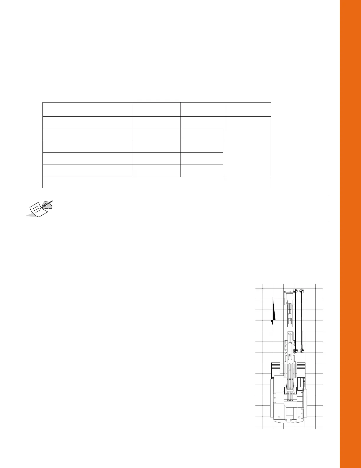
3. Positionthemachinedirectlynorth.Bothbucketedgeswill havethe
sameNorthingvalue(Figure72onpage52).
4. Retracttheelementsandthebucketsothatitiscurledinnearthe
machineandontheground.
5. RecordtheEastingvalueofonebucketcornerusingasurveyrover
(e.g.Easting
Rover‐Curl
=520.38).
6. RecordtheEastingvalueofthesamecornerwith3D‐MC(e.g.
Easting
3DMC‐Curl
=520.35).
Table7.ExampleCalculationswithoutaSurveyRover
Measurement Symbol Value Adjustment
Easting(Curled‐in) Easting
CURL
10425.67
Easting(Extended) Easting
EXT
10425.55
Difference(Curled‐Extended) Easting
Diff
‐0.12
Distance:MainAntennatoHub Distance
Main‐Hub
30.0
Distance:MaintoAuxAnte nna Distance
Main‐Aux
7.5
[‐0.12/4]=‐0.03
Negativevaluesshouldbesubtractedfromthe3D‐MCvalues,andpositivevaluesshouldbe
added.
bucket
curled in
bucket
extended