Verifying Setup
57
X‐63/X‐63i/X‐62/X‐33/X‐32InstallationandCalibrationManual P/N:7010‐0697
Method B: Without Using a Survey Rover
Beforeyoubegin,ensurethatallequipmentandmeasurementsareusingthe
sameunitsofmeasure(i.e.Meters,SurveyFeet,etc.).
MeasurewithBucket Curled‐in:
1. Positionthemachineonaflatsurface,andplaceahubinaflatopen
area.
2. Using3D‐MCasareference(inalocalizedproject),taptheElevation
ControlKey,theleftGPSinfo...button,andthentapthePositiontab.
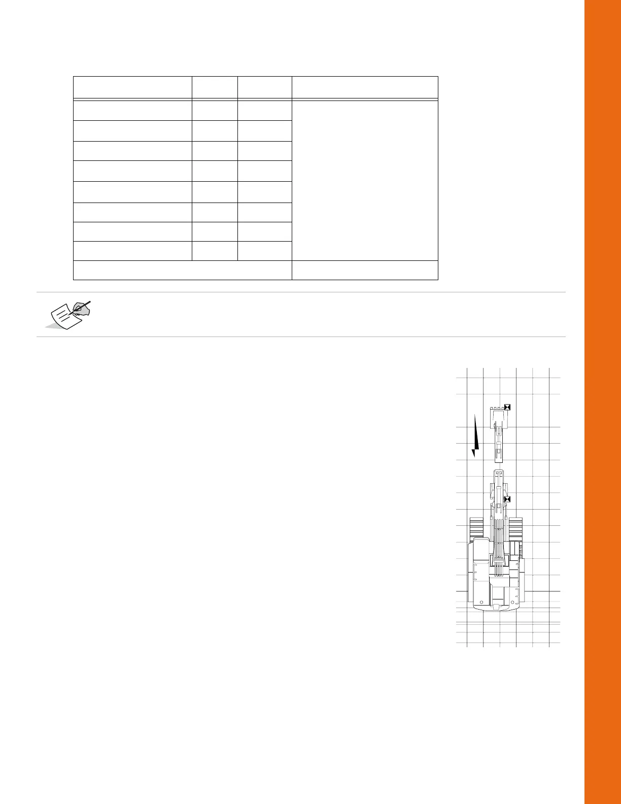
3. Positionthemachinedirectlynorth.Bothbucketedgeswill havethe
sameNorthingvalue(
Figure72onpage52).
4. Retracttheelementsandbucketsothatitiscurled‐innearthe
machine,andplaceabucketcorneronthehub.
5. From3D‐MC,recordtheEastingvalueofthebucketcorneryouchosein
step4(e.g.Easting
CURL
=10425.67).
MeasurewithBucket Extended:
1. Fullyextendtheelementsandbucketawayfromthemachine,
repositionthemachinedirectlynorth,andplacethebucketonthehub.
2. From3D‐MC,recordtheEastingvalueofthepreviouslychosenbucket
corner(e.g.Easting
EXT
=10425.55).
3. CalculatethedifferenceinEastingvalues(e.g.Easting
DIFF
=Easting
EXT
‐Easting
CURL
=‐0.12).
4. Withtheelementsextended,measurethe distancefromtheMainAntennatothebucketteeth
onthehub(e.g.Distance
Main‐Hub
=30.0).
5. MeasurethedistancebetweentheMainandAuxantennas(e.g.Distance
Main‐Aux
=7.5).
6. Calculatethedistanceratio(e.g.Ratio
Dist
=Distance
Main‐Hub
/Distance
Main‐Aux
=4).
Table6.ExampleofCalculationsUsingaSurveyRover
Measurement Symbol Value Adjustment
Curled‐in(Rover) A
rover
520.38
Curled‐in(3DMC) A
3DMC
520.35
Difference(Rover‐3DMC) A 0.03
Extended(Rover) B
rover
520.51
Extended(3DMC) B
3DMC
520.36
Difference(Rover‐3DMC) B 0.15
DistanceBetweenAntennas C 7.5
DistanceBetweenAandB D 20.0
[7.5*(0.03‐0.15)/20]=0.045
Negativevaluesshouldbesubtractedfromthe3D‐MCAuxAntenna‐to‐Boomlength
measurement,andpositivevaluesshouldbeadded.