Introduction
2DExcavatorIndicateSystems
7
X‐63/X‐63i/X‐62/X‐33/X‐32InstallationandCalibrationManual P/N:7010‐0697
2D Excavator Indicate Systems
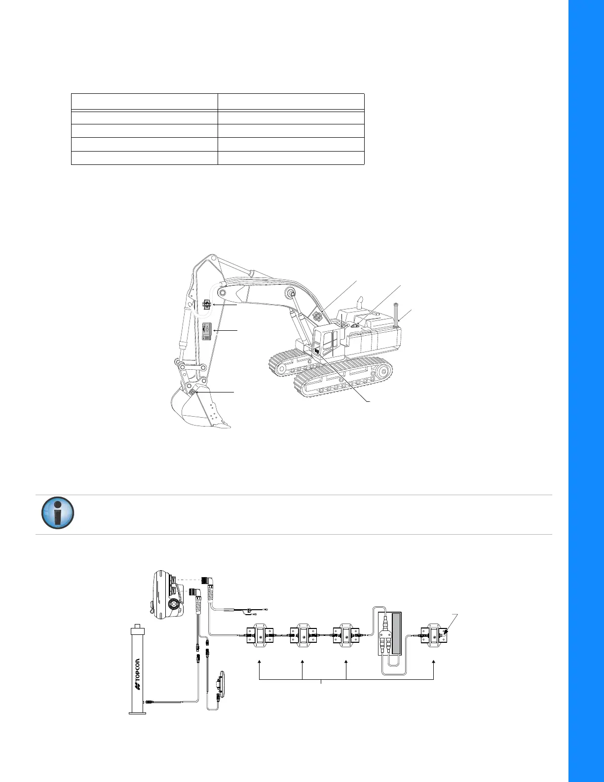
Table2liststhecomponentsofthedifferent2Dindicatesystems
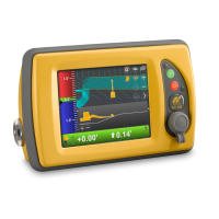
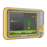
X-62
TheTS‐1TiltSensors,theGX‐60ControlBox,andtheLS‐B10WLaserReceivermakeuptheX‐62indicate
system.TheLS‐B10Waddsalaserheightreference,andiscalibratedforitslocationonthestickofthe
excavator.
Figure8:MachineComponentsoftheX‐62System
Figure9showsthebasiccablingconnectionsfortheX‐62system.Wheninstallingcomponents,use
theTopconsuppliedfuseorfusedpowerfromthemachineofthesamerating.
Figure9:BasicCableConnectionsfortheX‐62System
Table2.2DIndicateSystemComponents
X-62 X-32
TS-1 Tilt Sensors TS-i3 Tilt Sensors
GX-60 Control Box GX-30 Control Box
LS-B10W Laser Receiver MC-i3 GNSS Receiver
Compass Compass
Bucket
Sensor
LS-B10WLS-B10W
Laser ReceiverLaser Receiver
LS-B10W
Laser Receiver
Body
Sensor
Boom
Boom
SensorSensor
Boom
Sensor
StickStick
SensorSensor
Stick
Sensor
Compass
GX-60
Systemgroundmustbeconnectedtotheframesideofthegrounddisconnectswitch,not
directlytotheneg ativebatteryterminal.
TS-1 Tilt Sensors
Body Boom Stick Bucket
LS-B10W
Laser Receiver
And Bracket
-
+
Ground To Chassis
7.5 Amp
In-line Fuse
Required
Voltage Supply
(Switched Or
Unswitched Is
Acceptable)
Sensor
Terminator
Compass
Optional
Lightbar