Introduction
2DExcavatorIndicateSystems
8
X‐63/X‐63i/X‐62/X‐33/X‐32InstallationandCalibrationManual P/N:7010‐0697
X-32
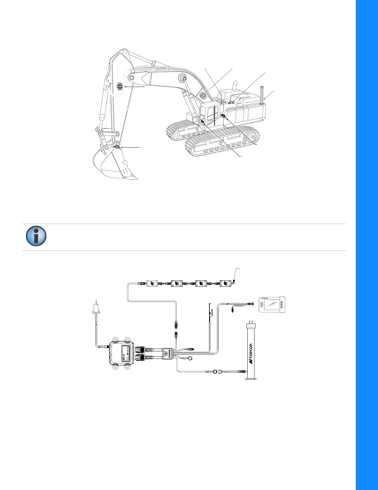
TheX‐32systemcontainsTS‐i3TiltSensors,theGX‐30Contr olBox,andtheMC‐i3GNSSReceiver.
Figure10:MachineComponentsoftheX‐32System
Figure11showsthebasiccablingconnectionsfortheX‐32system.Wheninstallingcomponents,use
theTopconsuppliedfuseorfusedpowerfromthemachineofthesamerating.
Figure11:BasicCableConnectionsoftheX‐32System
Bucket
Sensor
LS-B10W
Laser Receiver
Body
Sensor
Boom
Sensor
Boom
Sensor
Stick
Sensor
Stick
Sensor
GX-30
Compass
Radio Antenna
MC-i3
Systemgroundmustbeconnectedtotheframesideofthegrounddisconnectswitch,not
directlytotheneg ativebatteryterminal.
MC-i3
GX-30
TS-i3 Tilt Sensors
StickBoomBody Bucket
Serial
CAN
Compass
Sensor
Terminator
7.5 Amp
In-line Fuse
Required