Verifying Setup
56
X‐63/X‐63i/X‐62/X‐33/X‐32InstallationandCalibrationManual P/N:7010‐0697
Method A: Using a Survey Rover
Beforeyoubegin,ensurethatallequipmentandmeasurementsareusingthe
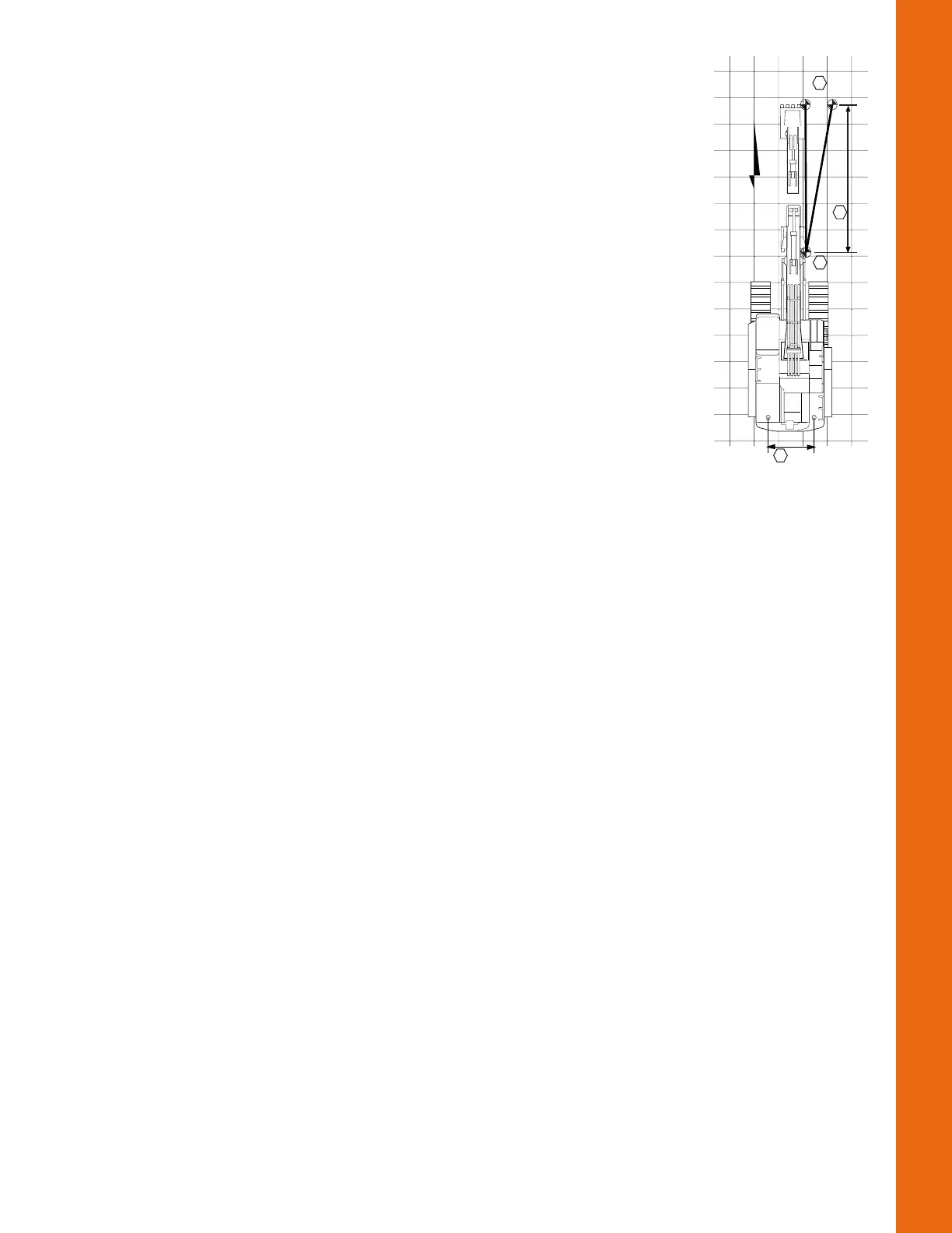
sameunitsofmeasure(i.e.Meters,SurveyFeet,etc.).Usingthediagramon
therightasareference,recordmeasurementsforthebucketcurled‐in(A),
extended(B),thedistancebetweenthetwoantennas(C),andthedifference
betweencurled‐inandextended(D).
MeasurewithBucket Curled‐in:
1. Positionthemachineonaflatandstablesurface.
2. Using3D‐MCasareference(inalocalizedproject),taptheElevation
ControlKey,theleftGPSinfo...button,andthentapthePosition
tab.
3. PositionthemachinedirectlyNorth(bothedgesofthebucketwill
havethesameNorthingvalue)(Figure72onpage52).
4. Retracttheelementsandthebucketsothatitiscurledinnearthe
machineandontheground.Markthiscurled‐inpositiononthe
ground.
5. RecordtheNorthingvalueofonecornerofthebuck etusingasurvey
rover(A
rover
).
6. RecordtheNorthingvalueofthesamecornerwith3D‐MC(A
3DMC
).
Calculatethedifferenceasfollows:A
=
A
rover
‐A
3DMC
MeasurewithBucket Extended:
1. Fullyextendtheelementsandbucketawayfromthemachinesothatthebucketisonthe
ground.Markthisextendedpositionontheground.
2. RecordtheNorthingvalueofthesamecornerofthebucketusingasurveyrover(B
rover
).
3. RecordtheNorthingvalueofthesamecornerwith3D‐MC(B
3DMC
).
4. Calculatethedifferenceasfollows: B=B
rover
‐B
3DMC
MeasureDistancesandCalculateAdjustments:
1. MeasurethedistancebetweentheMainAntennaandtheAuxAntenna(C).
2. Usemeasuringtapetomeasurethetotaldistancebetweenthecurled‐in(A)andextended(B)
lengths(D).
3. CalculatetheadjustmentneededfortheAuxAntenna‐to‐Boomlengthusingthefollowing
equation:Adjustment=[C*(A‐B)/D](see
Table6onpage57).
4. RepeatallstepsofMethodAtoverifythecorrection.
N
3DMC
0.15Ft
7.5Ft
Survey Rover
A
D
B
20Ft
0.03Ft
C
Two Machine Positions over Two Points