Introduction
2
X‐63/X ‐63i/X‐62/X‐33/X‐32Installationand Calibra tion Manual P/N:7010‐0697
Introduction
ThismanualdiscusseshowtoinstallandcalibratetheX‐63/X‐63i/X‐33GPSexcavatorindicatesystemsfor3D
control,andtheX‐62/X ‐32excavatorindicat esystemsfor2Dcontrol.
TheTS‐i3andTS‐1TiltSensors(917 4‐0001)usedintheTopconexcavatorsystemsmeasurethepitchandroll
angleofvariousmachineelements(Figure2).Eachsensoraccuratelymeasuresagravity‐ref erencedangleof
thebody,boom,stickandbucket,sendingthisangledatatoaGX‐60orGX‐30ControlBoxtoprovidepr ecise
grade.Eachsensorisconfiguredandcalibratedforitsspecificlocationontheexcavator.
Thebodysensorfunctionalityisuniqueasitmeasuresbothpitchandroll(crossslope)ofthemachine.
3D Excavator Indicate Systems
Table1liststhecomponentsofthedifferent3Dindicatesystems.
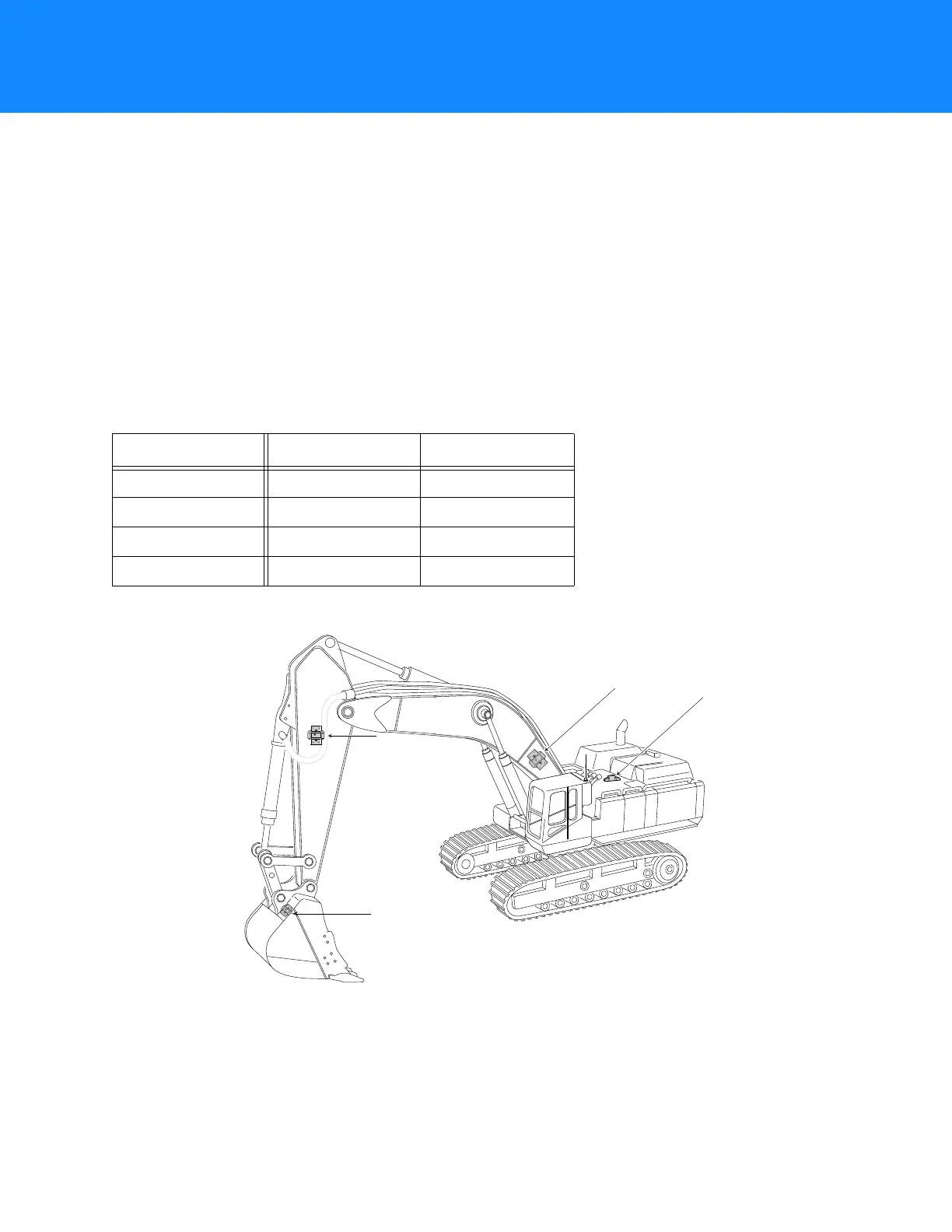
Figure2showsthepositionofthesensorsfor3Dindicatesystems.
Figure2:TiltSensorsonanExcavator
Table1.3DIndicateSystemComponents
X-63i X-63 X-33
TS-1 Tilt Sensors TS-1 Tilt Sensors TS-i3 Tilt Sensors
GX-60 Control Box GX-60 Control Box GX-30 Control Box
MC-i3 GNSS Receiver MC-R3 GNSS Receiver MC-i3 GNSS Receiver
GPS Antennas (2) GPS Antennas (2) GPS Antennas (2)
Bucket
Sensor
LS-B10WLS-B10W
Laser ReceiverLaser Receiver
Body
Sensor
Boom
Boom
SensorSensor
Boom
Sensor
StickStick
SensorSensor
Stick
Sensor