EasyManua.ls Logo

Toptech Systems MultiLoad II SCS User Manual

Default Icon
515 pages
To Next Page IconTo Next Page
To Previous Page IconTo Previous Page
Page #319 background image
Chapter 9 Weights & Measures
319
Firmware Version 3/4.31.37
Parameter
Description
API Name
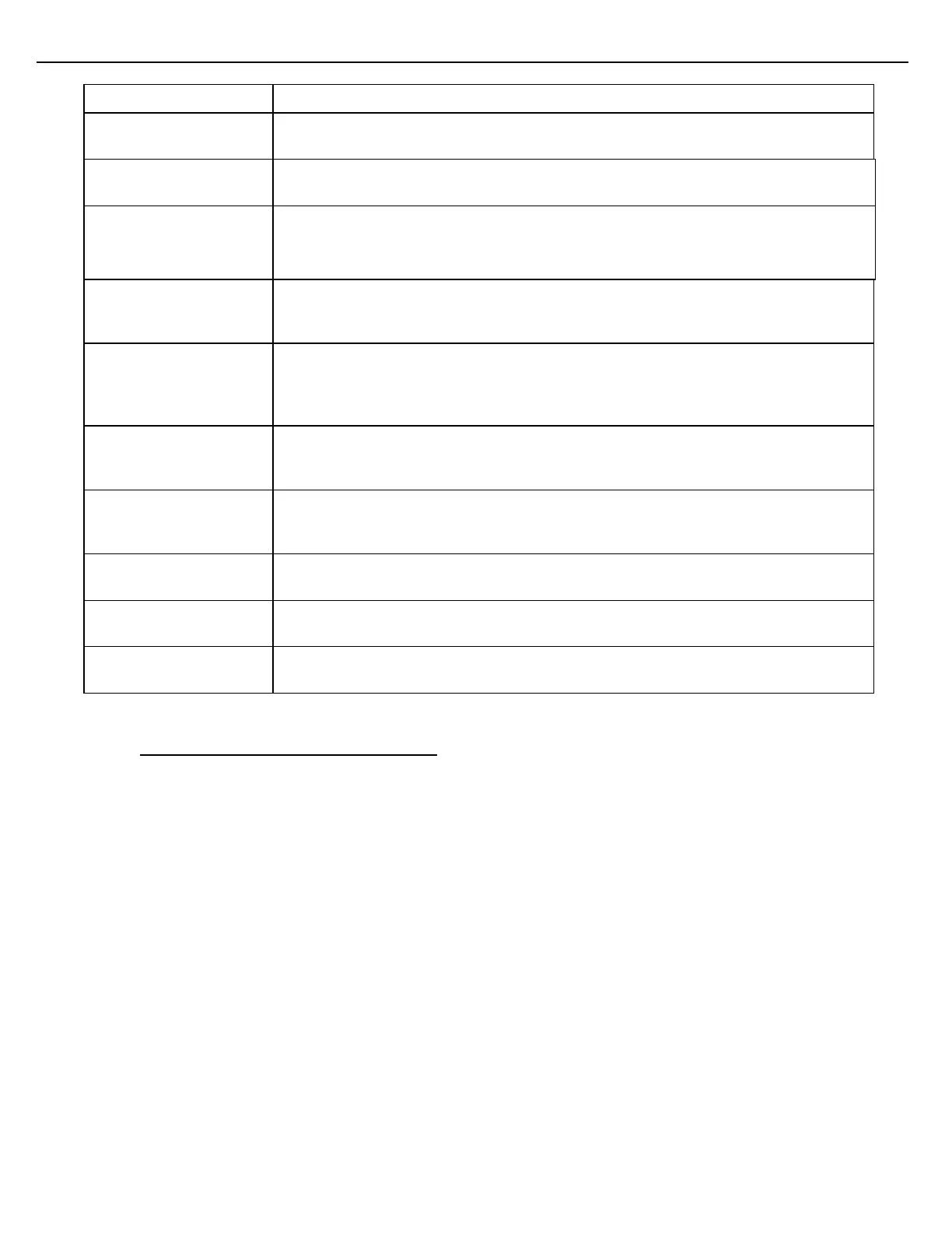
Select the desired API table to correct liquid volumes to a reference temperature.
Highlight the field and press Enter to scroll through the choices.
Test Temp
Enter a test temperature in this field. The temperature that is entered here will not
have any effect on actual measurement.
Test Density or
Test Relative Density or
Test API Gravity
Enter a test density, test relative density or test API Gravity in this field. The value
that is entered here will not have any effect on actual measurement.
API Gravity/Expansion
Coefficient
One of these fields will appear, depending on the API table selected. Enter the
requested value in this field. The value that is entered in this field will be used to
calculate VCF during operations.
Calculated VCF
The value in this field is the result of the API Test Temperature and the data in the
previous field (density, gravity, or expansion coefficient). This Calculated VCF is for
information only and has no affect on actual measurement. VCF is equal to CTL *
CPL.
Calculated CTL
The value in this field is the result of the API Test Temperature and the data in the
previous field (density, gravity, or expansion coefficient). This Calculated VCF is for
information only and has no affect on actual measurement.
Calculated CPL
The value in this field is the result of the API Test Temperature and the data in the
previous field (pressure). This Calculated VCF is for information only and has no
affect on actual measurement.
Corrected Relative
Density
This field will appear, depending on the API table selected. The value will show the
corrected Relative Density.
Corrected Density
This field will appear, depending on the API table selected. The value will show the
corrected Density.
Corrected Gravity
This field will appear, depending on the API table selected. The value will show the
corrected Gravity.
9.15 PRESSURE CALIBRATION FOR METERS
Use the Pressure screen to calibrate pressure for a meter.
1. From the Views & Inquiries Menu, choose Pressure.. After selecting the preset and meter, the Pressure
screen displays:

Table of Contents

Question and Answer IconNeed help?

Do you have a question about the Toptech Systems MultiLoad II SCS and is the answer not in the manual?

Toptech Systems MultiLoad II SCS Specifications

General IconGeneral
BrandToptech Systems
ModelMultiLoad II SCS
CategoryControl Unit
LanguageEnglish

Summary

CHAPTER 2 SYSTEM DESCRIPTION

2.11 Switch Access Control

Details how external access control switches limit access to Program Mode and W&M parameters.

2.11.4 Program Mode / W&M DIP / Security Bypass Switch

Explains how DIP switches on the CPU board can provide closure for Program Mode/W&M switch contacts.

2.14 MultiLoad II Configuration Tool

Describes the optional GUI configuration tool for setting up the system from a PC.

CHAPTER 3 GUI CONFIGURATION TOOL

3.13 Windows MultiMate Configuration Tool

Explains the procedure to install and run the MultiMate Configuration Tool program.

3.13.7 Update the Firmware Image in a MultiLoad II

Explains the two-step process for updating the firmware image in a MultiLoad II.

CHAPTER 4 GENERAL CONFIGURATION

4.2 Communication Setup

Explains how to define communication parameters for each serial communication port.

4.3 Network Setup

Details defining network parameters for the Ethernet port.

4.4 RCU General Setup

Specifies RCU communication address, enables/disables remote processing, and assigns configuration passwords.

4.4.1 Security Accounts Setup

Allows creation of User accounts with security levels to limit parameter changes.

4.5 RCU Setup

Configures how the MultiLoad II RCU unit will function, including driver language and card reader settings.

4.6 Security Setup

Details how users can change parameters based on their security level.

4.6.1 Password Security Setup

Sets up user account password policies, including minimum length and expiration.

4.6.2 Group Parameter Level Setup

Defines group-level security settings for parameters not covered by individual Equipment Setup settings.

4.6.3 External Access Level Setup

Assigns security levels to external sources like Network/Ethernet and Modbus.

4.8 Equipment Setup

Configures the Bay and its associated presets, meters, components, and additives.

4.8.1 Bay Setup

Configures all Bay level configurations, including number of presets, FCMs, and temperature units.

4.8.2 Preset Setup

Configures the characteristics of a load arm, including number of meters, components, and additives.

4.8.3 Meter Setup

Configures the characteristics of a product meter, including flow control module and side-stream settings.

4.8.4 Component Setup

Configures the characteristics of a component, including meter assignment and flow rates.

4.8.5 Additive Setup

Refers to section 6.6 for additive setup; notes that additives are not supported on MultiLoad II SCS.

4.8.6 Sampler Setup

Configures the characteristics of a sampler, including enable, FCM port, and volume per injection.

4.9 Tank Setup

Configures tank settings, including tank group, number, and active tank mode.

4.11 Alarm Setup

Defines alarm conditions and authorities at various configuration levels (Bay, Preset, Meter, etc.).

4.12 Local Product Definition and Assignment

Explains the purpose of Product Setup functions: define products and assign them to presets.

4.13 Product Setup

Guides the user to define products in Local mode, starting with base components, additives, and samplers.

4.15 Defining Saleable Products

Guides the user to define saleable products composed of base components and additives.

4.16 Preset Product Setup

Allows assigning defined Base Components, Additives, Samplers, and Saleable Products to a Preset.

4.17 Tank Product Setup

Assigns defined Base Component and Base Additive to a Tank.

4.20 Access IDs

Explains assigning Personal Identification Numbers (PINs) to MultiLoad II access cards.

CHAPTER 5 PRODUCT FLOW CONTROL

5.2 Single Product Delivery

Discusses the five stages of single component product delivery: Low Flow Start, High Flow, 1st Stage Trip, 2nd Stage Trip, Final Trip.

5.2.5 2”-3” Digital Control Valves

Discusses digital control valves, needle valve adjustments, and an alternative flow algorithm.

5.2.6 Adaptive Digital Control Algorithm

Explains the algorithm for increasing accuracy of targeting flow rates.

5.2.8 Analog Valves

Details analog valves operating from a 4-20mA signal for proportional opening.

5.3 Sequential Blending (Excluding SMP)

Explains Sequential Blending for delivering multiple components one at a time.

5.3.1 Sequential Blending Configuration

Guides on configuring parameters for sequential blending at Preset, Meter, and Component levels.

5.4 Ratio Blending (Excluding SMP)

Describes Ratio Blending, delivering multiple components simultaneously while maintaining blend ratio.

5.4.1 Ratio Blending Configuration

Details configuring presets for ratio blending, including number of flow meters and components.

5.5 Side-Stream Blending (Excluding SMP)

Explains Side-Stream blending, where minor components are injected upstream of the major component's flow meter.

5.5.1 Simple Side-Stream Blender Configuration

Guides on configuring a load arm as a side-stream blender, starting at the preset-level.

5.6 Hybrid Blending (Excluding SMP)

Describes hybrid blending schemes with multiple side-streams or major components through the primary stream.

5.6.2 Sequential Blending with Side-Stream

Details sequential blending with a side-stream component as a hybrid-blending scheme.

5.6.3 Ratio Blending with Side-Stream

Explains that side-stream meters can be added to meter runs for ratio blending.

5.8 Line Flush (Excluding SMP)

Describes the Line Flush feature for laying the line with a specific component at the end of the load.

5.10 Calibration Using Meter Factor Linearization

Explains meter factor determination during proving tests and the Meter Factor Linearization feature.

CHAPTER 6 ADDITIVE CONTROL

6.5 Additive Control Methods

Details five additive control methods: Piston Only, Piston with Input, Solenoid & Pulser Input, Common Meter, and Analog Valve.

6.5.9 Method 5 – Common Meter with Multiple Additives

Explains how multiple additives can be delivered through a common injector.

6.6 General Additive Setup

Provides general setup for additives, including enable, FCM, port, and type parameters.

6.7 Additive Calibration

Describes two additive calibration methods: Additive Cal (one additive) and Remote Calibration (multiple additives).

6.9 Remote Additive Calibration

Enables technicians to test injectors one after another without returning to the MultiLoad II.

6.11 Additive Flush Features

Supports applications with demanding flush requirements, such as red dye, using flush pumps and valves.

CHAPTER 7 SWING ARM SETUP AND OPERATION (EXCLUDING SMP)

7.2 Swing Arm Operation

Explains how a swing arm's status (Idle, Absent, Active) affects bay operations and alarms.

7.4 Swing Arm Configuration

Provides steps for configuring two bays to share one or more swing arms, designating secondary RCUs.

CHAPTER 8 DIAGNOSTICS

8.2 Card Reader (Excluding SMP)

Explains how to use the Card Reader function to verify operation of proximity card readers and driver cards.

8.3 iButton Reader (Excluding SMP)

Describes using the iBUTTON function to verify operation of iButton and driver cards.

8.4 Loopback Test

Details the Loopback Test for checking Host COM Port transmit/receive capabilities and serial communication.

8.5 Serial Port Test

Explains verifying serial port hardware health using a special loop back cable.

8.7 Network Test

Explains verifying or troubleshooting the network connection between MultiLoad II and Host (TMS) system.

8.11 FCM Communications

Determines if internal I/O board or external FCMs are communicating with the MultiLoad II.

8.12 PCM Communications

Determines if a PCM is communicating with the MultiLoad II.

8.18 Meter Diagnostics

Diagnoses wiring or hardware problems by testing control from MultiLoad II to devices like digital control valves and flow meters.

8.19 Digital Control Valve Test

Tests digital control valves by automatically opening and closing them, measuring speeds.

8.24 Custom Logic

Allows looking at the live value of each line in custom logic.

CHAPTER 9 WEIGHTS & MEASURES

9.2 Access Restrictions to W&M Parameters

Details the three methods of write-access to W&M parameters: manual, remote, and SD card upload.

9.3 Weights & Measures Change Log and Metrological Parameter Security

Discusses the last 1,000 W&M parameter changes logged and security restrictions.

9.4 Volume Correction Factor Features

Explains the calculation of net volumes using Gross Volume, Meter Factor, and Volume Correction Factor (VCF).

9.5 Net and Mass Calculations

Details the calculation of mass corrected to density, using three types of densities.

9.5.4 API Table VCF Calculators

Details entering test values to calculate VCF factors for CTL and CPL.

9.7 Multiload Sequential Blending Calculations

Details calculations for sequential blending, including Regular and Premium meter level values.

9.8 Multiload Ratio Blending Calculations

Explains calculations for ratio blending, covering Regular and Premium meter and component level values.

9.9 Multiload Side-Stream Blending Calculations

Details calculations for side-stream blending, covering Regular/Ethanol and Regular/Premium streams.

9.10 Multiload Sequential with Ratio Blending Calculations

Explains calculations for sequential blending with ratio blending, covering Regular/Premium main streams and Ethanol side-stream.

9.11 Multiload Ratio with Side-Stream Blending Calculations

Details calculations for ratio blending with side-stream, covering Regular/Ethanol and Premium main streams.

9.13 Temperature Calibration for Meters

Guides on using the Temperature screen to calibrate temperature for a meter.

9.14 Temperature Compensation and VCF Calculator

Explains configuring API tables for Volume Correction for Temperature (CTL) and Pressure (CPL).

9.15 Pressure Calibration for Meters

Guides on using the Pressure screen to calibrate pressure for a meter.

9.16 Density Calibration

Explains using the Density screen to calibrate density for a meter.

9.17 Relative Density Calibration

Guides on using the Relative Density screen to calibrate relative density for a meter.

9.18 API Gravity Calibration

Explains using the API Gravity screen to calibrate API Gravity for a meter.

9.19 BSW1 Calibration

Guides on using the BSW1 screen to calibrate the BSW1 sensor for a preset.

9.20 BSW2 Calibration

Explains using the BSW screen to calibrate the BSW2 sensor for a preset.

CHAPTER 10 VIEWS AND INQUIRIES

10.3 Viewing Totalizers

Explains selecting Totalizers from the menu to view Preset, Meter, Component, and Additive totalizers.

10.11 Viewing Transactions

Guides on inquiring transaction data using the Bill of Lading (BOL) function.

10.13 View Weights and Measures Change Log

Guides on selecting W&M Change Log to view parameter changes and print the log.

CHAPTER 11 SD CARD

11.6 Load Firmware

Explains selecting a firmware file (.bin) to load, requiring W&M switch active.

CHAPTER 12 OPERATION

12.3 Driver Card or Keypad Access

Explains the initial authorization process involving driver card or access ID/driver number and PIN.

12.4 Remote Control Operation

Provides detailed driver instructions for operating MultiLoad II in Remote mode with a host system (TMS).

12.5 Local (Standalone) Operation

Describes operation in Local mode where product and access info are stored in non-volatile memory.

12.5.2 Product Database

Details the Product database categories: Base Product definitions, Saleable Product definitions, Preset Authorized products, Base Component Assignments, Base Additive Assignments.

12.5.5 Configuring MultiLoad II for Local Mode

Explains changing one parameter (Remote Processing) to operate in standalone mode.

12.5.7 Local Authorization

Details the local mode authorization process involving driver card/access ID, PIN, and configurable prompts.

12.6 Automatic Proving Function

Describes the feature for flow meter proving by delivering a predetermined volume into a calibrated vessel.

12.6.1 Using the Proving Feature

Provides steps for activating Weights and Measures switch and performing a single product transaction.

12.7 Ending Sampler Batch (SCS Only)

Explains how to end a Sampler Batch and generate a Batch Report, saving it as a CSV file.

CHAPTER 13 CUSTOM LOGIC

13.2 Custom Logic Groups

Explains that each line of custom logic can be assigned values, operations, and parameters.

CHAPTER 14 WEB INTERFACE

CHAPTER 15 MULTILOAD HELP

CHAPTER 16 FIRMWARE REVISION HISTORY

16.2 Firmware Changes

Provides a summary of changes made in various firmware builds (e.g., ML, ML1, SMP).

Related product manuals