To create a face on a part:
1. From the Conversational tab, select the Face tab.
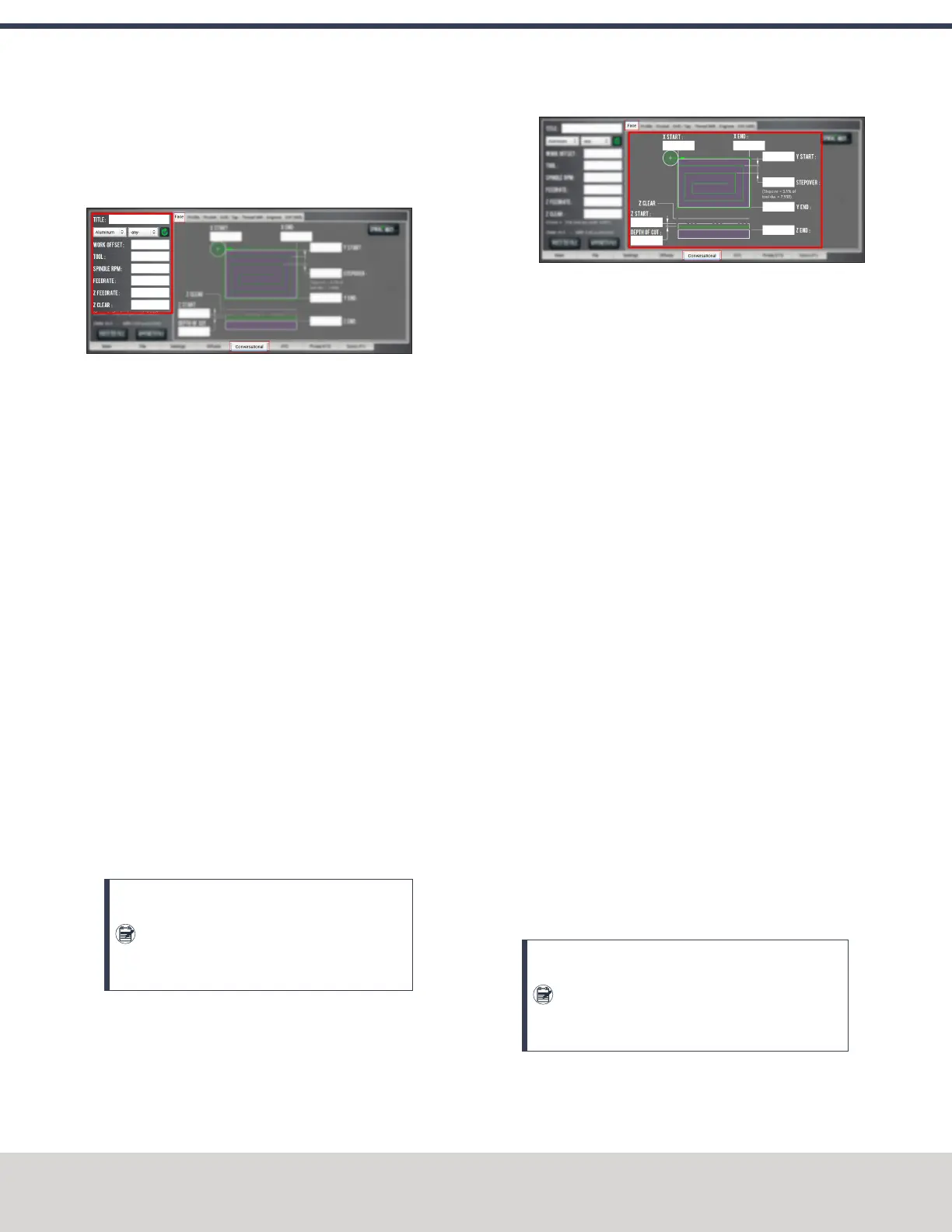
2. From the Conversational DROs group, set the
parameters for the facing operation.
Figure 7-15: Conversational DROs on the Face tab.
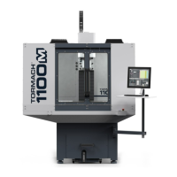
3. Work through the program-specific DRO fields:
a. In the X Start DROfield and the XEnd DROfield, type
the location of the workpiece edges. We recommend
using the rear left corner of the part for the X Start
value.
b. In the YStart DRO field and the YEnd DROfield, type
the location of the workpiece edges. We recommend
using the front right corner of the part for the Y End
value.
c. In the Stepover DROfield, type the required distance
between tool paths. To prevent uncut areas in the
spiral corners, we recommend limiting this value to
80% of the tool diameter. For information, see
"Facing Reference" (on the next page).
d. In the Z Start DROfield and the Z End DROfield, type
the location of the first and last Z passes. For a single
Z pass at the location typed in the Z End DRO field,
type a value of 0 or a full Z range value into the
Depth of Cut DRO field.
e. In the Depth of Cut DROfield, type the desired
amount of material to remove.
Note: The depth of cut is later adjusted
within the Z range so that each pass in the Z
range has the same depth (rather than the
last Z pass having a short depth of cut).
Figure 7-16: Program-specific DROs on the Face
tab.
About Facing
Face milling is the process of cutting a surface that's
perpendicular to the axis of the cutting tool. A facing program
is usually used to cut an accurate, finished top surface on a
rough piece of stock material. After a facing program is
complete, tool marks remain — creating a fairly flat surface,
with microscopic height differences.
Facing in PathPilot
When using a facing routine, each tool pass along the X-/Y-axis
begins off to the side of the workpiece to avoid plunging into
the workpiece. To compensate for this procedure, PathPilot
sets lead-in tool paths outside of the workpiece using the
part's work offsets, the tool's diameter, and the
predetermined stepover value. PathPilot also adjusts the depth
of cut to make sure each tool pass has the same depth, rather
than cutting a short depth on the last pass of the program.
During a facing routine, PathPilot does the following:
1. Moves the machine to the predefined G30 position, or
the tool change position.
2. If required, performs or requests a tool change.
3. Makes a rapid move in the X and Y direction to the
beginning of the workpiece.
4. Makes a rapid move in the Z direction to the predefined
Z Clear position.
5. Begins the cut in the X/Yplane at an adjusted Z depth of
cut.
Note: The value entered into the Depth of Cut
DRO field is adjusted within the Z range (the
value entered into the Z End DROfield minus
the value entered into the Z Start DROfield).
6. Makes cuts in a rectangular spiral from the workpiece
perimeter to the workpiece center.
©Tormach® 2020
Specifications subject to change without notice.
Page 110 Tormach 1100MX Operator's Manual (Version 0720A)
For the most recent version, see tormach.com/support
7: PATHPILOT TOOLS AND FEATURES


 To Next Page