8: BASIC OPERATIONS
be running (like “wiggler”-style edgefinders or coaxial
indicators).
The machine's spindle rotates either clockwise (forward) or
counterclockwise (reverse) at a specified spindle speed.
8.4.3 Spindle Controls Reference
The spindle speed is measured in revolutions per minute
(RPM).
Two speed ranges are available:
l
Low70 rpmto 2000 rpm
l
High250 rpm to 10,000 rpm
Use the low speed range when you're using larger cutting
tools, or machining materials with lower surface speeds (like
steel or stainless steel).
Use the high speed range when you're using smaller cutting
tools, or machining materials with higher surface speeds (like
aluminum, brass, or plastic).
To move your spindle speed range from one to the other, see
"Change the Spindle Speed Range" (on the previous page).
8.5 LOAD G-CODE
To run a G-code program on a PathPilot controller, you must
first verify that the file is on the controller. For more
information on transferring and moving files, see "Transfer
Files to and From the Controller" (page104).
To load G-code:
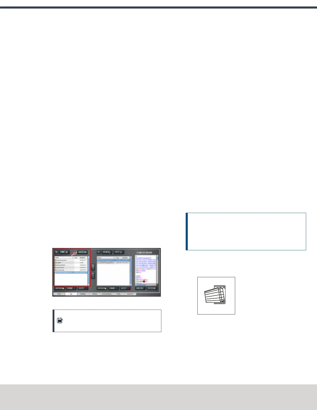
1. From the File tab, in the Controller Files window, select
the desired .nc file.
2. Select Load G-Code.
Figure 8-7: Controller Files window on the File tab.
Note: This function is only available for files
stored on the PathPilot controller.
PathPilot loads the G-code file and opens the Main tab.
8.6 SET UP TOOLING
Before you begin machining, you must put your cutting tools in
tool holders and measure the tool length offsets for each tool.
l "Install a Tool in a Set Screw Tool Holder" (below)
l "Install a Tool in an ER Collet Tool Holder" (below)
l "Install a Drill Chuck in a Jacobs Taper Arbor" (on the
next page)
8.6.1 Install a Tool in a Set Screw Tool Holder
1. Clean the shank of the tool holder with a clean rag.
Verify that the shank is free of any grease or oil.
2. Remove the set screw from the tool holder with a hex
wrench.
3. Put the desired cutting tool into the tool holder.
4. Replace the set screw in the tool holder, and then
completely tighten it with a hex wrench.
8.6.2 Install a Tool in an ER Collet Tool Holder
The ER20 collet is self-extracting: the collet must be mounted
in the nut before the nut and collet assembly are put into the
collet holder.
If you look closely, you'll notice that the collet nut isn't
symmetrical — an area of the retaining ring is cut away. When
the collet is correctly mounted in the nut, the collet is pushed
forward and out of the collet holder taper while the nut is
slightly loosened (which results in self-extraction).
NOTICE! If you don't install the collet in the order
specified, there's a risk that the collet and/or nut could be
damaged, and the collet's holding capacity could be
reduced.
To install a tool in an ERcollet tool holder:
1. Hold the collet at an angle, and then insert it into the
collet nut as shown in the following image.
Figure 8-8: A collet inserted into the collet nut.
©Tormach® 2020
Specifications subject to change without notice.
Page 151 Tormach 1100MX Operator's Manual (Version 0720A)
For the most recent version, see tormach.com/support
 Loading...


