7: PATHPILOT TOOLS AND FEATURES
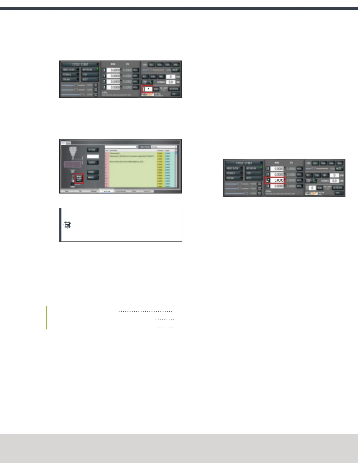
6. From the PathPilot interface, type the tool number in the
Tool DROfield. Then select the Enter key.
Figure 7-54: Tool DRO field.
7. Jog the Z-axis down (-Z) until it is above the ETS.
8. From the Offsets tab, on the Tool tab, select Move and
Set Tool Length.
Figure 7-55: Tool tab on the Offsets tab.
Note: Regardless of the initial feed rate, the
final touch off feed rate while using an ETS is
2-1/2 in. per minute (IPM).
9. From the Tool Table window, in the Length column,
verify that the length of the tool is correct.
Use a Zero Setting Gauge to Measure Tools
This procedure sets the tool length offset using a known
reference height and a zero setting gauge.
Complete the following steps in the order listed:
Set a Known Reference Height 129
Verify the Calibration of the Zero Setting Gauge 129
Measure Tools Using a Known Reference Height 129
Set a Known Reference Height
1. Identify a precision surface to use as a reference surface
(like a 1-2-3 Block Set), and put it below the spindle.
2. Verify that the drive dogs won't contact the reference
surface before the end face of the spindle.
3. Set a new, unused work offset:from the PathPilot
interface, on the Main tab, in the MDI Line DROfield,
type a work offset. Then select the Enter key.
4. If there's already a tool in the spindle, remove it.
5. From the PathPilot interface, in the Tool DROfield, type
0. Then select the Enter key.
6. Slowly jog the Z-axis down (-Z) until it's 0.04 in. (1 mm)
from the reference surface.
7. Put a piece of paper on the reference surface.
8. Slowly jog the Z-axis down (-Z), and slowly move the
piece of paper back-and-forth.
9. Stop jogging the Z-axis when you feel a light pull on the
piece of paper, which indicates that it is in contact with
the end face of the spindle.
10. From the PathPilot interface, in the Z-axis work offset
DROfield, type the thickness of the piece of paper. Then
select the Enter key.
The reference surface is now set as the Z zero position in
the current coordinate system.
11. To set the tool length offset, go to "Measure Tools Using
a Known Reference Height" (page160).
Verify the Calibration of the Zero Setting Gauge
1. Use the provided dowel pin to compress the setting face
of the Zero Setting Gauge to the level of the ground
reference surface.
2. Adjust the bezel of the indicator dial to read zero. The
Zero Setting gauge dial will now read “0” when
compressed to the height of the ground reference
surface.
3. Measure the height of the ground reference surface
from the bottom surface of the Zero Setting gauge using
a micrometer. Note the measured height for later.
Measure Tools Using a Known Reference Height
1. Verify that the reference surface is still on the machine
table with the piece of paper.
2. From the PathPilot interface, on the Offsets tab, in the
Tool Table window, type a description for the tool.
3. Put the tool holder into the spindle.
4. From the PathPilot interface, in the Tool DRO field, type
the number of the tool. Then select the Enter key.
©Tormach® 2020
Specifications subject to change without notice.
Page 129 Tormach 1100MX Operator's Manual (Version 0720A)
For the most recent version, see tormach.com/support