9. Follow the on-screen instructions to set the spindle's
tool change rotation position:
a. Rotate the spindle clockwise in the fork by hand.
Then, select OK.
b. Rotate the spindle counterclockwise in the fork by
hand. Then, select OK.
The tool change rotation position has now been set.
In the dialog box that displays, select OK.
10. Manually move the ATC back to the retracted position.
WARNING! Crush Hazard: If the ATC isn't
completely retracted, it could move once the
air is reconnected. When you reconnect the air,
you must keep your hands away from the ATC.
11. Reconnect the air.
12. Remove the tool from the spindle.
13. Move the Z-axis up: in the MDILine DROfield, type G20
G53 G1 Z0 F20. Then select the Enter key.
14. On the ATC tab, select Go To Tray Load Position. Then,
manually load a tool into the fork.
15. Orient the spindle:from the PathPilot interface, in the
MDI Line DRO field, type M19 R0 Q10. Then select the
Enter key.
16. Open the drawbar: on the ATC tab, select Collet, and
wait until the LED toggles from Closed to Open.
Note: You must verify that the drawbar is open
(and not just that the brake is engaged) before
you continue.
17. Verify that the spindle is concentric with the tool: slowly
jog the Z-axis down and, depending on the result, do one
of the following:
l
If the Spindle is Concentric with the Tool You've
completed the alignments.
l
If Adjustments are Required Go to Step 18.
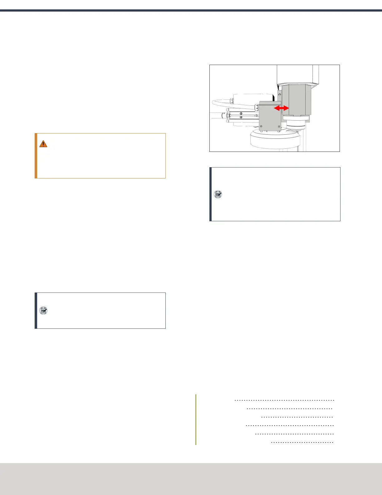
18. Determine if the tray must move left or right. Use two
wrenches to loosen the jam nut on the end of the
cylinder rod, making sure that you don't spin the rod end
when adjusting the jam nut. Then, either turn the rod
end one-half turn further on to the cylinder rod to move
the tool tray to the left, or turn it one-half turn off of the
cylinder rod to move the tool tray to the right. Once
finished, tighten the jam nut.
Figure 4-70: Moving the tool tray left or right.
Note: Don't move the tool tray more than 0.100
in. in either direction (left or right). If you do,
the tool tray will exceed the Tray In sensor,
which affects how ATC operations are
communicated to PathPilot.
19. Adjust for the ATC's backlash: apply light pressure
forward and backward on the carousel; then, from the
PathPilot interface, on the ATC tab, select ++ or -- until
there's equal space on the front and the back of the
BT30 taper.
20. Verify that, from the Status tab, the ATC Tray In LEDis
still illuminated.
If the LEDisn't illuminated, examine the tool tray. It may
have exceeded the Tray In sensor during adjustments in
the previous step.
21. Repeat adjustments until the tool's shank is concentric
with the spindle.
22. Move the Z-axis up: in the MDILine DROfield, type G20
G53 G1 Z0 F20. Then select the Enter key.
23. Remove the tool from the ATC. Then, select Retract.
4.8.5 Install the 4th Axis
Complete the following steps in the order listed:
Required Tools 65
Unpack the 4th Axis 65
Lubricate the Rotary Table 65
Adjust the Backlash 66
Mount the Rotary Table 67
Install the A-Axis Motor Driver 67
©Tormach® 2020
Specifications subject to change without notice.
Page 64 Tormach 1100MX Operator's Manual (Version 0720A)
For the most recent version, see tormach.com/support
4: INSTALLATION
 Loading...


