3. Attach each of the four casters to the bottom of the
coolant tank with four M6 × 12 mm socket head cap
screws, spring washers, and flat washers.
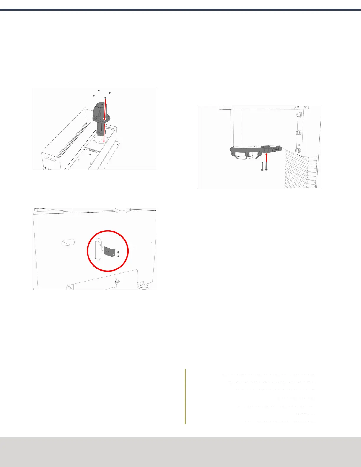
4. Attach the coolant pump to the coolant tank with the
four screws provided.
Figure 4-48: Coolant pump and its hardware moving
into the coolant tank.
5. Remove the coolant hose bracket from the rear of the
Machine Stand. Set the hardware aside.
Figure 4-49: Coolant hose bracket and its hardware
removed from the Machine Stand.
6. Attach the provided Y-fitting to the coolant hose bracket,
and then install the coolant hose bracket back on the
Machine Stand using the hardware that you set aside in
Step 5.
7. Put the coiled coolant hose into one side of the Y-fitting.
8. Put the provided plug into the remaining side of the Y-
fitting.
9. Cut a 3 in. (76 mm) piece of the coolant hose with snips.
10. Put the newly cut piece of the coolant hose into the
bottom of the Y-fitting. Then, put the provided elbow
onto the its loose end.
11. Put the full-length coolant hose into the open end of the
elbow.
12. Route the loose end of the full-length coolant hose
through the Machine Stand, through the energy chain,
and to the spindle head.
13. Attach the coolant manifold to the spindle nose with the
two screws provided.
Figure 4-50: Attaching the coolant manifold to the
spindle nose.
14. Put the loose end of the full-length coolant hose into the
coolant manifold.
15. Route the loose end of the coiled coolant hose through
the rear of the Machine Stand, and then put it into the
elbow on the coolant pump.
16. Move the coolant tank into the Machine Stand.
17. Route the power cord on the coolant pump to the rear of
the electrical cabinet, and connect it to the Coolant
PumpPower outlet.
18. Verify that the coolant setup operates properly:
a. From the PathPilot interface, on the Main tab, select
Coolant.
The coolant pump powers on.
b. Select Coolant again.
The coolant pump powers off.
4.8.4 Install the Automatic Tool Changer (ATC)
Complete the following steps in the order listed:
Required Tools 57
Air Requirements 57
Prepare the Machine 57
Disassemble the Power Drawbar Button 57
Install the Air Cylinder 58
Mount the Automatic Tool Changer (ATC) Bracket 58
Install the Main Assembly 59
©Tormach® 2020
Specifications subject to change without notice.
Page 56 Tormach 1100MX Operator's Manual (Version 0720A)
For the most recent version, see tormach.com/support
4: INSTALLATION
 Loading...


