4: INSTALLATION
6. Select FWD.
The spindle starts.
7. From the Status tab, make sure that the VFD Running
green light comes on.
Figure 4-66: VFDRunning light on the Status tab.
Note: If the VFDRunning light did not come on
in the previous step, we can help. Email
support@tormach.com to contact Tormach
Technical Support for guidance on how to
proceed.
8. Select Stop.
The spindle stops.
Adjust the Tool Alignment and Set the Tool Tray Height
and Encoder Position
1. From the PathPilot interface, on the ATC tab, select Ref
Tool Tray.
Figure 4-67: Ref Tool Tray button on the ATCtab.
The tool tray spins.
Note: You're only required to reference the tool
tray once, unlike the mill axes’ referencing
procedure.
2. If you haven't already done so, load a tool into the
spindle.
3. Manually rotate the spindle two revolutions by hand.
The encoder has now been oriented.
4. Disconnect the air from the machine.
5. While manually advancing the tool tray toward the
spindle, align the fork with the tool. Complete the
following steps in the order listed:
a. Slowly jog the Z-axis up or down until the groove in
the fork aligns with the groove in the tool holder.
b. Determine if the tray must move clockwise or
counterclockwise to align the fork with the tool
holder. From the PathPilot interface, in the ATC tab,
either select -- to step the tool tray counterclockwise
or ++ to step the tool tray clockwise.
c. Fully seat the ATC to its tray load position, verifying
that the tool and its drive dog slots are fully inserted
into the fork.
6. Verify that, from the Status tab, the ATC Tray In LEDis
still illuminated.
If the LEDisn't illuminated, examine the tool tray. It may
have exceeded the Tray In sensor during adjustments in
the previous step.
7. On the ATC tab, select Set TCPOS.
Figure 4-68: Set TCPOS button on the ATC tab.
The tool change position has now been set.
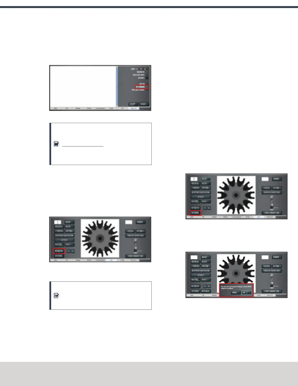
8. Select Set TC M19. Then, in the dialog box that displays,
select OK.
Figure 4-69: Confirmation dialog box to change the
spindle's alignment position.
©Tormach® 2020
Specifications subject to change without notice.
Page 63 Tormach 1100MX Operator's Manual (Version 0720A)
For the most recent version, see tormach.com/support

 Loading...


