5. Inspect the item(s):
l Photograph any damage that may have occurred
during shipping.
l Verify the received goods against the packing list.
If there is any damage or shortages, you must contact
Tormach within 30 days of receipt. Email
support@tormach.com to contact Tormach Technical
Support for guidance on how to proceed.
6. Find the accessory box inside the Machine Stand, which
contains the feet for the Machine Stand. Set it aside for
later installation.
7. Remove the shipping bolts on the coolant tank, and then
move it out of the Machine Stand.
8. Locate and remove all other items and hardware
components in the Machine Stand and in the coolant
tank. Then, set them all aside for later installation.
9. Lift the coolant tank off the pallet, and set it aside for
later installation.
10. Remove the four nuts securing the Machine Stand to the
pallet with a 17 mm wrench.
11. To install the Machine Stand's feet, you must first lay it
on its front surface. Put a large piece of cardboard (or
similar) on the floor to protect the Machine Stand.
CAUTION! Team Lift Required:You must have
the aid of more than one person to lift and
move the object. The object is heavy, and lifting
it by yourself can cause serious injury.
12. Lift the Machine Stand off the pallet, and set it down on
the cardboard that you put on the floor in Step 11.
Figure 4-1: Cardboard on the floor to set the Machine
Stand on.
13. Open the accessory box that you set aside in Step 6, and
then identify the hardware inside (which is used to
assemble the feet for the Machine Stand).
Note: There are four large spacers in the
accessory box that are used to assemble the
feet for a 770Mmill. If you're assembling the
feet for an 1100M mill, discard the spacers.
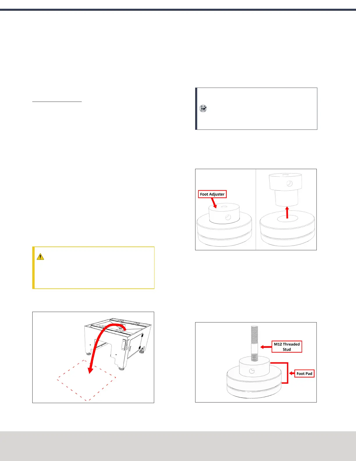
14. Identify the foot pad from the accessory box, and remove
the foot adjuster as shown in the following image. Then,
apply Anti-Seize to both components, and reassemble
the foot pad.
Figure 4-2: Disassembling the foot pad to apply Anti-
Seize on each component.
15. Put the foot adjuster back into the base of the foot pad,
but don't tighten it completely. Leave two threads visible
so that you can adjust the stand up or down later in this
procedure.
16. Put the threaded end of one M12 stud into each foot
pad.
Figure 4-3: Machine Stand foot assembly.
©Tormach® 2020
Specifications subject to change without notice.
Page 40 Tormach 1100MX Operator's Manual (Version 0720A)
For the most recent version, see tormach.com/support
4: INSTALLATION
 Loading...


