4 Replacement Procedures 4.11 Cover assembly
4.11 Cover assembly
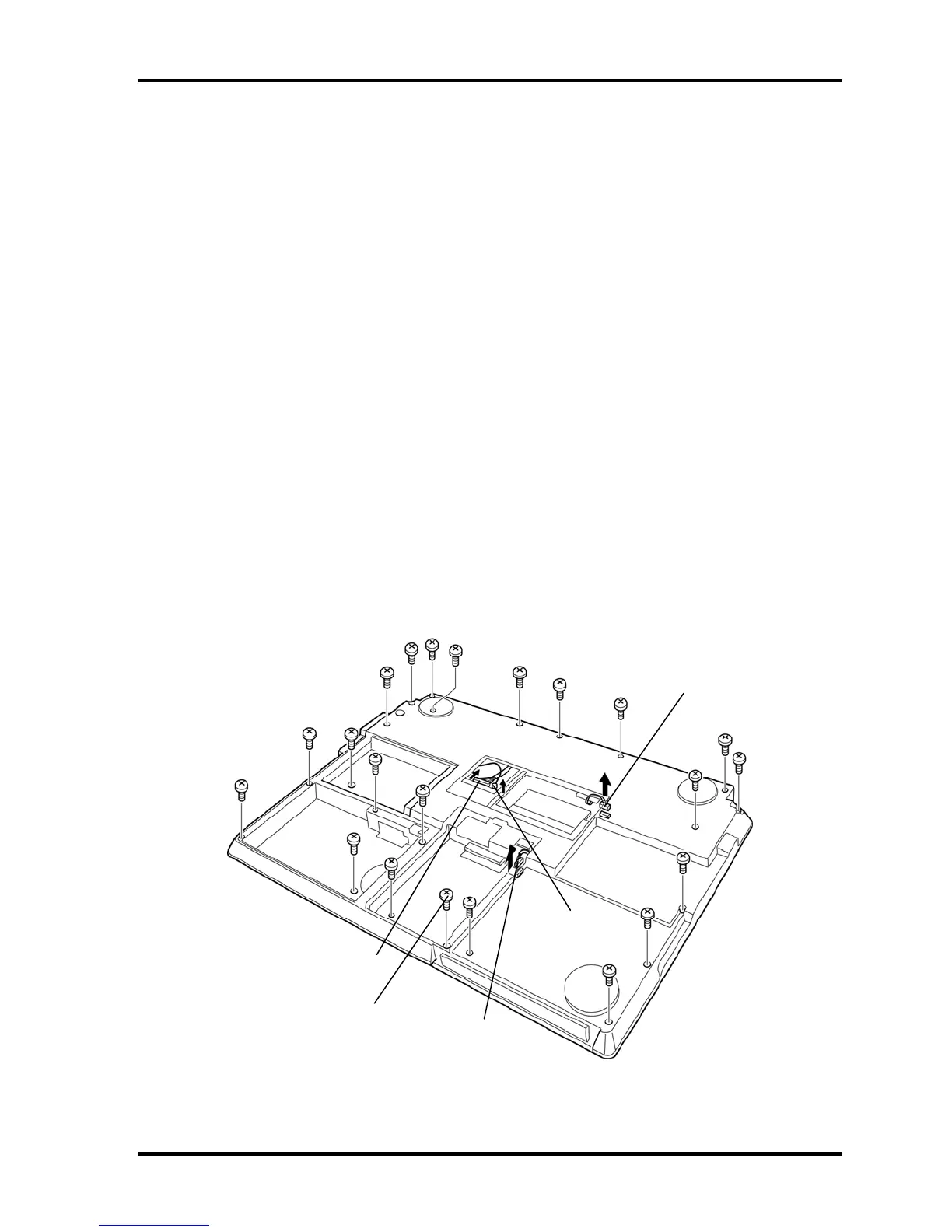
Removing the Cover assembly
The following describes the procedure for removing the cover assembly (See Figure 4-15 to
4-17).
1. Turn over the computer and disconnect the GPU fan cable from the connector
CN8781 on the system board.
2. Disconnect the analog TV turner cable and analog TV turner antenna cable from
the analog TV tuner.
3. Disconnect the speaker AMP cable from the connector CN6480 on the system board.
4. Remove the following screws securing the cover assembly.
• M2.0×4B BIND screw ×1 (Described as "4" in the figure)
• M2.5×6B FLAT BIND screw ×4 or ×3 (Described as "6" in the figure)
• M2.5×8B FLAT BIND screw ×3 (Described as "8" in the figure)
• M2.5×16B FLAT BIND screw ×14 (Described as "16" in the figure)
“4”
“16”
“16”
“16”
“16”
“16”
“8”
“16”
“16”
“16”
“16”
“16”
“8”
“16”
“16”
“8”
“6”
“6”
“6”
“16”
“16”
Speaker AMP cable
Connected to CN6480
GPU fan cable
Connected to CN8781
Analog TV turner cable
Analog TV turner
antenna cable
“6”
*This screw doesn't exist
for the HD-DVD model.
Figure 4-15 Removing the cover assembly (1)
4-28 [CONFIDENTIAL] QOSMIO G30 Maintenance Manual (960-546)
 Loading...