E6582233
H-8
8
(Continued)
Item displayed
Panel
operated
LED
displa
Communic
ation No.
Description
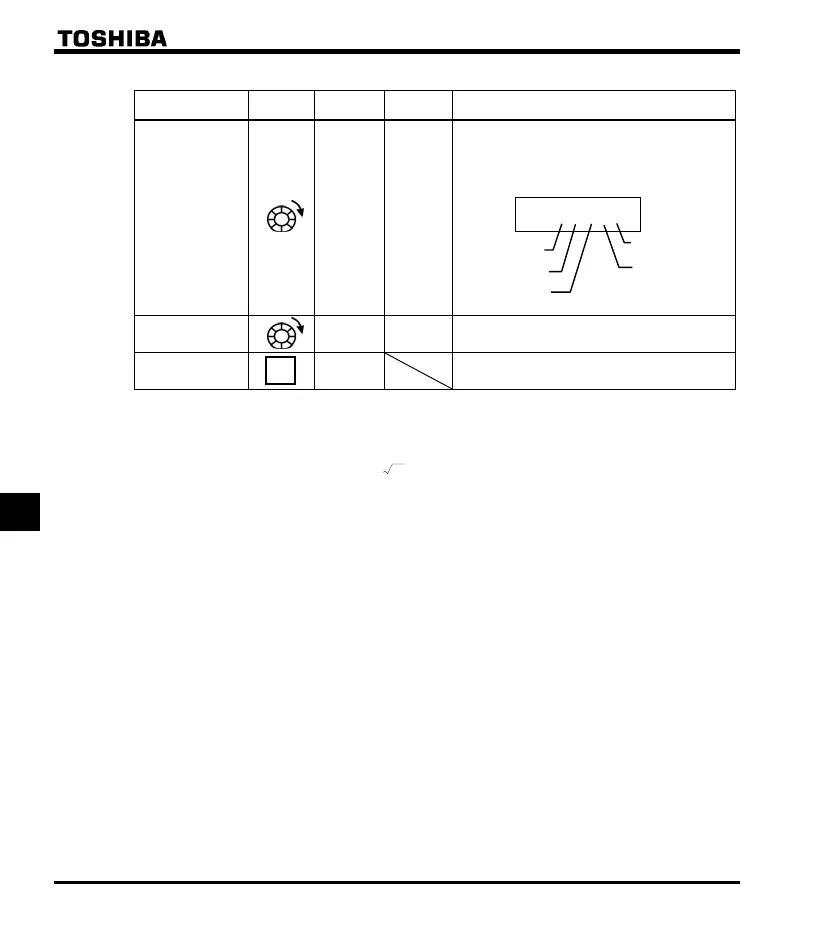
Parts replacement
alarm information
m }}}}i FE79
The ON/OFF status of each of the cooling fan,
circuit board capacitor, main circuit capacitor of
parts replacement alarm or cumulative operation
time are displayed in bits.
ON :
OFF:
Cumulative
operation time
FE14
The cumulative operation time is displayed.
(0.01=1 hour, 1.00=100 hours)
Default display
mode
The cause of the trip is displayed.
Note 1: The characters to the left disappear above 100 Hz. (Ex: 120 Hz is )
Note 2: You can switch between % and A (ampere)/V (volt), using the parameter (current/voltage unit
selection).
Note 3: The input (DC) voltage displayed is 1/
2
times as large as the rectified d.c. input voltage.
Note 4: If = 2 (Logic input): VI bar is activated depend on VI terminal ON/OFF.
If
= 0, 1 or 3 (Voltage/current input): VI bar is always OFF.
Note 5: If
= 0 (Logic output): Out bar is activated depend on OUT terminal ON/OFF.
If
= 1 (Pulse train output): OUT bar is always OFF.
Note 6: Past trip records are displayed in the following sequence: 1 (latest trip record)
234 (oldest trip
record). If no trip occurred in the past, the message “
” will be displayed. Details on past trip
record 1, 2, 3 or 4 can be displayed by pressing the center of the setting dial when past trip 1, 2, 3 or 4 is
displayed. Refer to section 8.2.2 for details.
Note 7: Parts replacement alarm is displayed based on the value calculated from the annual average ambient
temperature specified using
, the ON time of the inverter, the operating time of the motor and the
output current ( load factor). Use this alarm as a guide only, since it is based on a rough estimation.
Note 8: The cumulative operation time increments only when the machine is in operation.
Note 9: If there is no trip record,
nerr is displayed.
Note 10: Of the items displayed on the monitor, the reference values of items expressed in percent are listed below.
Load current: The current monitored is displayed. The unit can be switched to A
(amperes).
Input voltage: The voltage displayed is the voltage determined by converting the voltage
measured in the DC section into an AC voltage. The reference value
(100% value) is 400 volts for 400V models. The unit can be switched to V
(volts).
Note 7
Note 8
MODE
}}}}i
Cooling fan
Cumulative
operation time
Control circuit board
capacitor
Main circuit
capacitor
Number of starting

 Loading...


