Fig. 2.2 Robot base set bolts
(3) Bolts for each joint
Make sure, using the hexagonal wrench key, that the bolts for the axis 1 and 2
joints (i.e., bolts for clamping each reduction gear and arm) are tightened
completely. If loosened, tighten them completely.
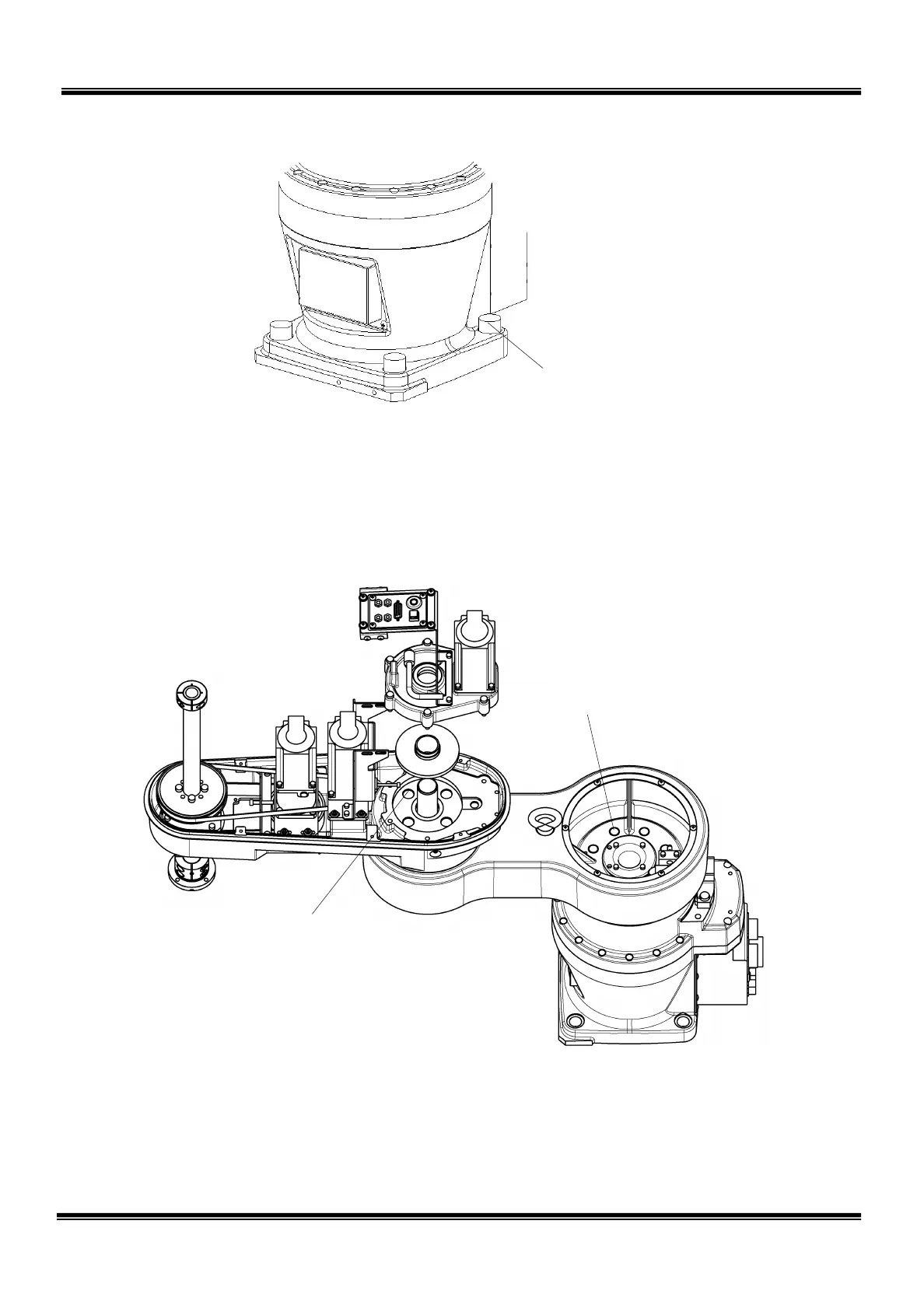
Fig. 2.3 Axes 1 and 2 set bolts
Main robot installation bolt
M16 x 4 pcs.; Recommended
clamping torque 170 N
·m
For how to remove the arm cover 1
attached to the arm 1, see Para. 2.4.2.
x 8 pcs.; Recommended clamping
·m
Axis 2 joint clamp bolt
M10 x 4 pcs.; Recommended clamping
torque 54 N
·m
* DO NOT tighten with clamping torque
exceeding 54
N·m.
For how to remove the axis 2 gear case
and center gear, see Para. 2.5.5.
STE 85306
– 19 –
 Loading...


