8) Draw out the cables and air tubes thus disconnected up to the upper side of the
arm 2.
As the inner diameter of the center shaft is small, observe the following order,
taking careful precautions not to damage the cables and connectors when
disconnecting the cables.
Air tubes → Power drive cables (small connectors) → Encoder cables (large
connectors)
Especially, when disconnecting the encoder cable connectors, pull them out
one by one so as to arrange them vertically. DO NOT pull them out by force.
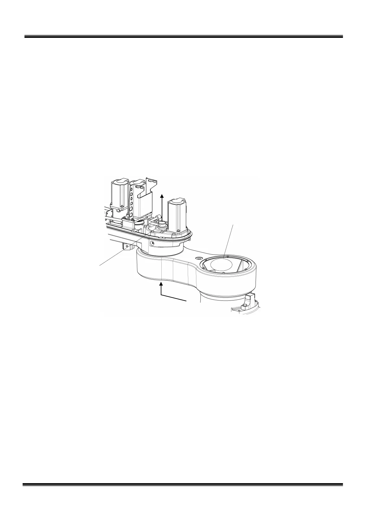
9) Remove the six (6) bolts (M6 × 35) securing the axis 2 gear case. Remove the
axis 3 tension adjustment bolt (M4 × 35) also. When dismantling the gear
case, provide a waste cloth, etc. as the grease is filled in the gear case. When
this happens, be sure to remove the “O” ring. There is no problem when the
bearing remains set.
The cables are connector-
connected at thi
s position.
Direction in which
cables are drawn out.
Direction in which cables are drawn out.
STE 85306
– 36 –
 Loading...


