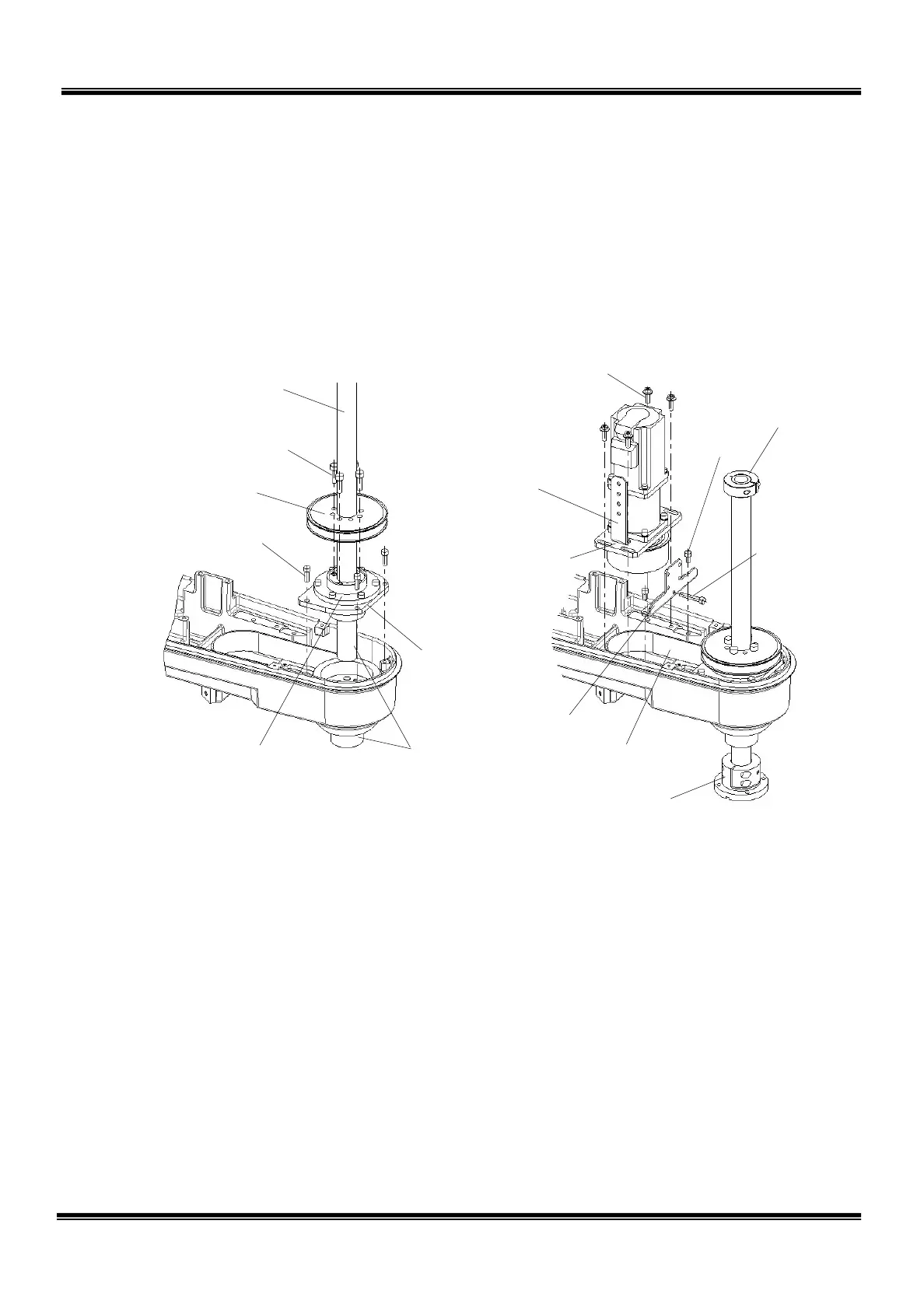
14) Attach the tool flange and stopper to the ball screw shaft.
15) Attach the guide to the arm 2 with the two (2) bolts (M5 × 10).
16) Temporarily set the motor base which was disconnected in Step 6) above to the
arm 2 with the four (4) flange head bolts (M5 × 16) after setting the axis 4 timing
belt to the axis 4 motor pulley. Also mount the axis 4 tension adjustment bolt
(M5 × 30).
17) While pushing the axis 4 motor base by means of the axis 4 tension adjustment
bolt, measure the tension on the tension meter. At a position where the
tension has reached 320 to 380 N, tighten the flange head bolts.
The values used for the tension meter are tabled below.
M6×20
Recommended clamping
torque: 17 N·m
M5×16
Recommended clamping
torque: 8.8 N·
M5×16
Recommended clamping
torque: 8.8 N·
Align the phases
and insert.
STE 85306
– 51 –
 Loading...


