Piping and Connections
102 CLCH-SVX07K-EN
recommends installing a plug to facilitate cleaning of the
trap. The drain connection sizes are:
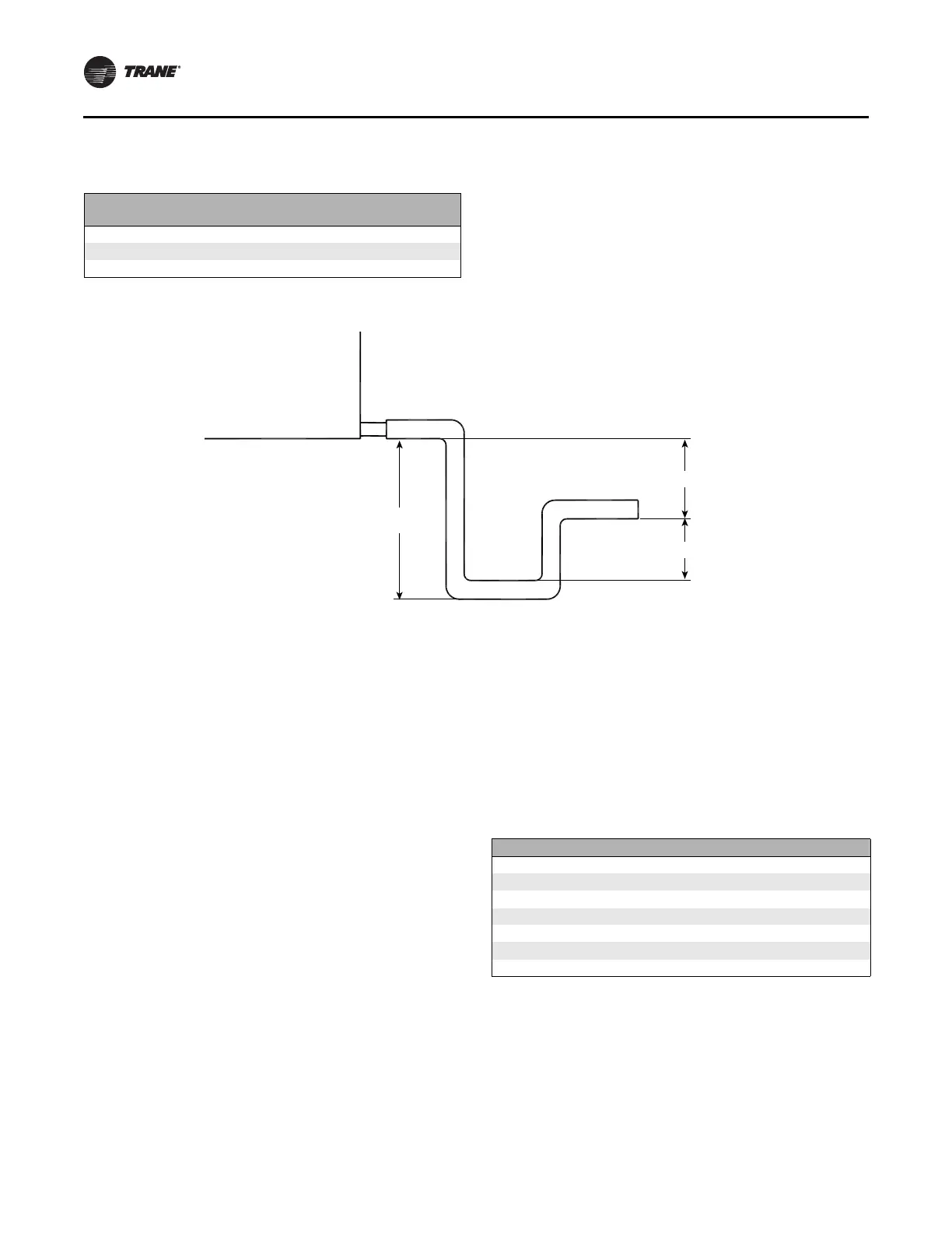
Figure 35 illustrates the proper trapping, piping, and
operation of the trap. Use the formula under the figure to
determine the correct minimum depth for the condensate
trap. If a section has a drain pan for cleaning purposes
only, it does not need a trap; however, a cap or shutoff
valve should be installed on the drain connection. Only
sections handling condensate, such as a cooling coil
section or moisture eliminator section, require a trap.
Steam Coil Piping
Air handlers fitted with steam coils have labeled holes for
piping penetrations. Figure 133 illustrates a typical steam
coil piping configuration. See Table 36 for the codes of
system components in these figures.
The coil condensate return line must be piped full size of
the condensate trap connection, except for a short nipple
screwed directly into the coil header’s condensate return
tapping. Do not bush or reduce the coil return trapping
size.
Unit size
NPT (national pipe thread) external
connection
3-30 1-inch
35-57 1 1/4 inch
66-120 1 1/2 inch
Table 35. Drain pan trapping for negative and positive pressure applications
H
J
L
Drain pan trapping for section
under negative pressure
L = H + J + pipe diameter where:
H = 1 inch for each inch of negative
pressure plus 1 inch
J = 1/2 H
Drain pan trapping for section
under positive pressure
L = H + J + pipe diameter where:
H = 1/2 inch (minimum)
J = 1/2 inch plus the unit positive static
pressure at coil discharge
(loaded filters)
Negative pressure Positive pressure
Table 36. Code of system components for piping figures
Code System component
FT Float and thermostatic steam trap
GV Gate valve
OV Automatic two-position (ON-OFF) control valve
VB Vacuum breaker
ST Strainer
AV Automatic or manual air vent
MV Modulating control valve