Component Installation
CLCH-SVX07K-EN 73
Diffusers
Diffuser sections are usually placed between a fan and a
downstream coil or filter. Because placement is critical to
unit performance, verify the correct placement of the
diffuser section before assembling the unit.
Fans
The fan section can be configured as either draw-thru or
blow-thru. Review the submittals and unit tagging
information prior to assembly to determine placement.
Fan Isolation
The fan-and-motor assembly is internally isolated. The fan
and motor bases are bolted to a minimum of four spring
isolators. The isolators are secured to the fan section
support base.
Shipping tie-down bolts are bolted adjacent to the
isolators between the fan isolation base and the isolator
support frame. The shipping tie-downs secure the
isolation base to the support assembly to prevent any
damage to the fan section during shipment.
Note: Remove the tie-downs only if the factory-provided
isolation is to be used.
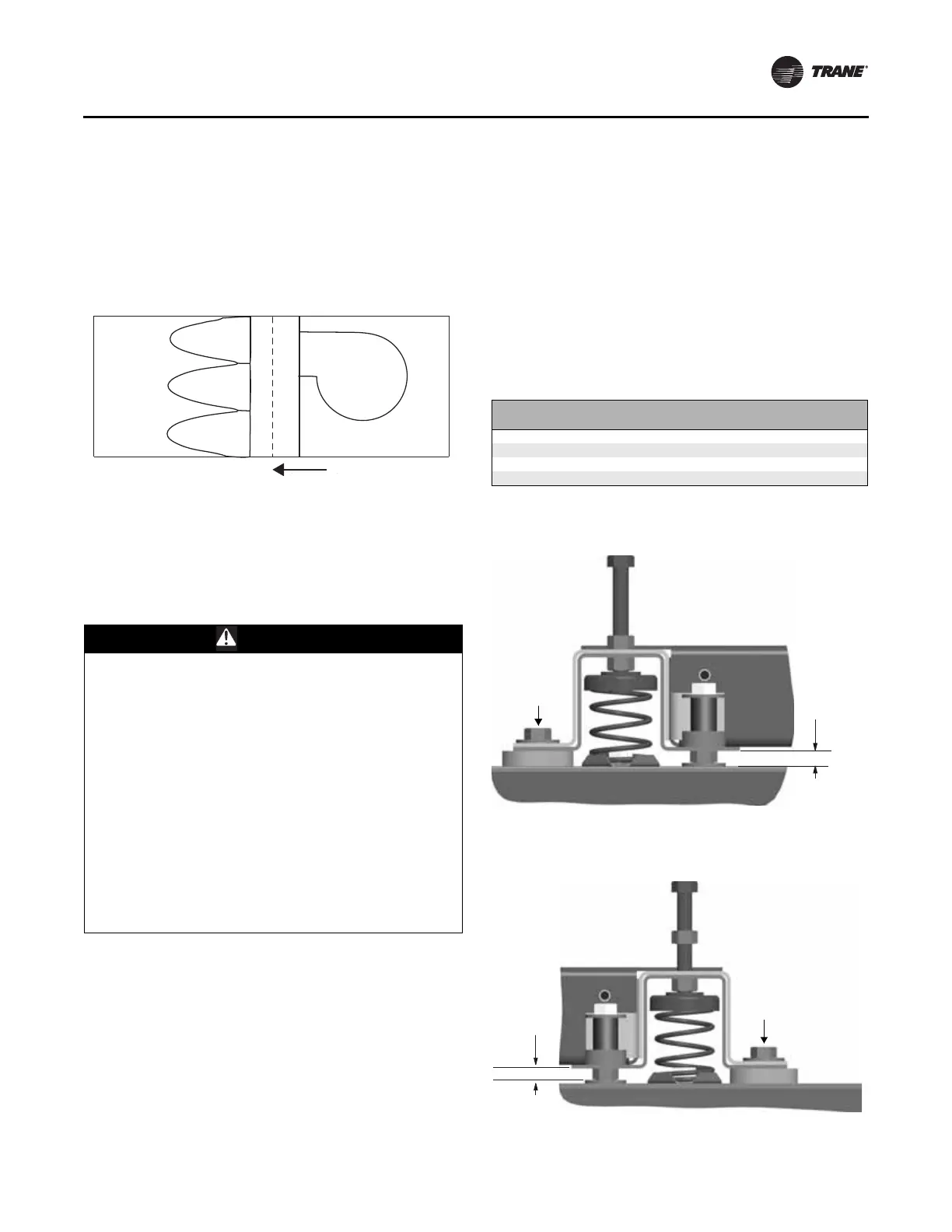
Adjusting the Isolators
Once the shipping tie-downs are removed and the internal
isolation is released, it may be necessary to adjust the
isolators to achieve the proper operation height of the fan
and motor isolation base.
Minimum required clearances are listed in Table 33. To
determine the isolator clearances on all unit sizes,
measure between the top of the cabinet channel and the
bottom of the isolation base channel.
Figure 92. Diffuser placement sizes 3 to 120
WARNING
Hazardous Service Procedures!
Failure to follow all of the safety warnings provided,
could result in death or serious injury. The maintenance
and troubleshooting procedures recommended in this
manual could result in exposure to electrical,
mechanical or other potential safety hazards. Always
refer to the safety warnings provided throughout this
manual concerning these procedures. Unless specified
otherwise, disconnect all electrical power including
remote disconnect and discharge all energy storing
devices such as capacitors before servicing. Follow
proper lockout/tagout procedures to ensure the power
can not be inadvertently energized. When necessary to
work with live electrical components, have a qualified
licensed electrician or other individual who has been
trained in handling live electrical components perform
these tasks.
Table 33. Minimum isolator clearances (inches)
Unit Size Fan Type
Required
Clearance
3–8 FC, BC, Plenum 1.0
10–30 FC, AF, Plenum 0.5
35-57 FC, AF, Plenum 0.5
66-120 FC, AF, Plenum 1.0
Figure 93. Isolator adjustment for unit sizes 3-8
Figure 94. Isolator adjustment for unit sizes 10-30
Required
clearance
Tiedown
Required
clearance
Tiedown