Installation - Electrical
116 CLCH-SVX07K-EN
Typical wiring schematics for VFDs and starters are shown
in Figure 155 and Figure 156, respectively. Unit specific
wiring schematics are shipped with each unit.
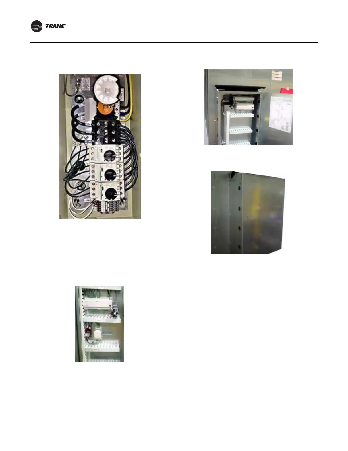
All units with starters or VFDs that have direct-digital
controllers (DDCs) are provided with line voltage to 24 Vac
power transformers as shown in Figure 149.
When provided, the line voltage to 24 Vac transformers are
factory wired to the supply fan power feed. All units with
factory-mounted controllers, and no starters or VFDs, are
provided with 120 Vac to 24 Vac control transformers, as
shown in Figure 150, and require a separate 120V field
connection.
As with starters or VFDs, units intended for indoor use are
available with DDCs mounted internally (see Figure 149)
or externally (seeFigure 150 and Figure 151), while units
intended for outdoor use are only available with internally
mounted DDCs.
In units with 24Vac LED marine lights, the lights are wired
together to a single switch located in the controls interface
module. Figure 151 shows a typical mounting of the
controls interface module with an externally mounted
controller. When DDCs are provided, the lighting circuit is
powered from the DDC power feed and does not require a
separate power source. When marine lights are provided
without DDCs, the lighting circuit requires a separate 120V
field connection that powers the lights through a 120V to
24Vac power transformer.
A mounted GFCI receptacle is provided for all units that
have DDCs or marine lights. The receptacle is mounted in
the controls interface module (see Figure 151) with the
unit light switch. The receptacle requires a separate 120V
power feed.
The electric heat door may have a solenoid locking
mechanism to prevent opening the control panel while the
electric heater is energized.
Field installed DDC control devices:
Figure 148. External motorized impeller control panel
(MICP)
Figure 149. Controller - internally mounted
Figure 150. Controller - externally mounted
Figure 151. Externally mounted control box