Start-Up
CLCH-SVX07K-EN 137
Wiring
The transmitter requires 24VDC/24VAC power on
terminals 1 (+) and 2 (ground) of the transmitter. When the
airflow measurement system is ordered with a factory-
mounted UC600 controller, the 24 VDC power will be
supplied.
In the absence of a factory-mounted UC600 controller, the
installing contractor must ensure the transmitter has
24VDC/24VAC power.
Transmitter Sizing
The Trane specification requires that the flow meter option
have a total accuracy of 5 percent. The total accuracy is a
combination of:
• how accurately the flow meter itself is in sensing
airflow
• how accurately the transmitter senses the differential
pressure
• how accurately the controller translates the signal
from the transmitter to a differential pressure.
Selecting the proper transmitter is critical in order to get
accurate airflow measurements. How accurately the
transmitter senses the differential pressure is dependent
on:
• the pressure range selected
• the accuracy of the selected transmitter
Trane air handlers use a 0-5 inch, 0-10 inch, or 0-25 inch
w.g. range transmitter as standard. To sufficiently cover
VAV turndown on the smallest fans with the above range,
a transmitter with an accuracy of 0.25 percent (full scale) is
used as standard. If a field-provided transmitter with a
lower accuracy is selected, the range should be chosen
closer to the actual, maximum pressure differential
expected for the application.
The transmitter outputs a signal that represents the
differential pressure which is used to calculate airflow. To
adequately calculate and display the airflow for the
smaller fans, ensure that the analog input is programmed
with enough decimal places to sufficiently represent the
pressure differential being measured.
Note: The transmitter is factory-calibrated to the range
selected and cannot be significantly adjusted to
“tighten” the range closer to the pressure being
read for the given application.
Available Transmitters
• TDR00729: 0-5”
• TDR00730: 0-10”
• TDR00731: 0-25”
Transmitter Calibration
The transmitter is factory-calibrated to a specific pressure
range with a 0-5 inch, 0-10 inch, or 0-25 inch w.g. range
being used in most cases. To check calibration and to
adjust if necessary, consult the transmitter manufacturer
or the factory for specific procedures.
The transmitter outputs a linear, 2-10 VDC signal
representing a differential pressure measurement. With
this measurement, the airflow through the fan can be
calculated using the following equation:
Significant differences in elevation and/or temperature
will affect the density of air. For air at a constant, non-
standard density, a field-obtained K factor can be used.
Alternatively, the following equation can be used to
continuously correct the equation above:
Note: Alternative units, including SI, can be used in place
of the IP units above although the K-factor must be
converted appropriately.
Setup details are available on the HUB - DOC-107523.
Maintenance
For a typical HVAC environment - especially with upstream
filtration - there should be little to no required
maintenance. In extreme cases or for mishaps (bearing
grease in the taps for example), the flow meter is easily
cleanable. The fan inlet airflow measuring system is
extremely simple: a few pressure taps, a few fittings, and
some tubing. Although unlikely, if any tap were to get
clogged, simply disconnect each side of the transmitter
and blast air in a reverse direction through the system.
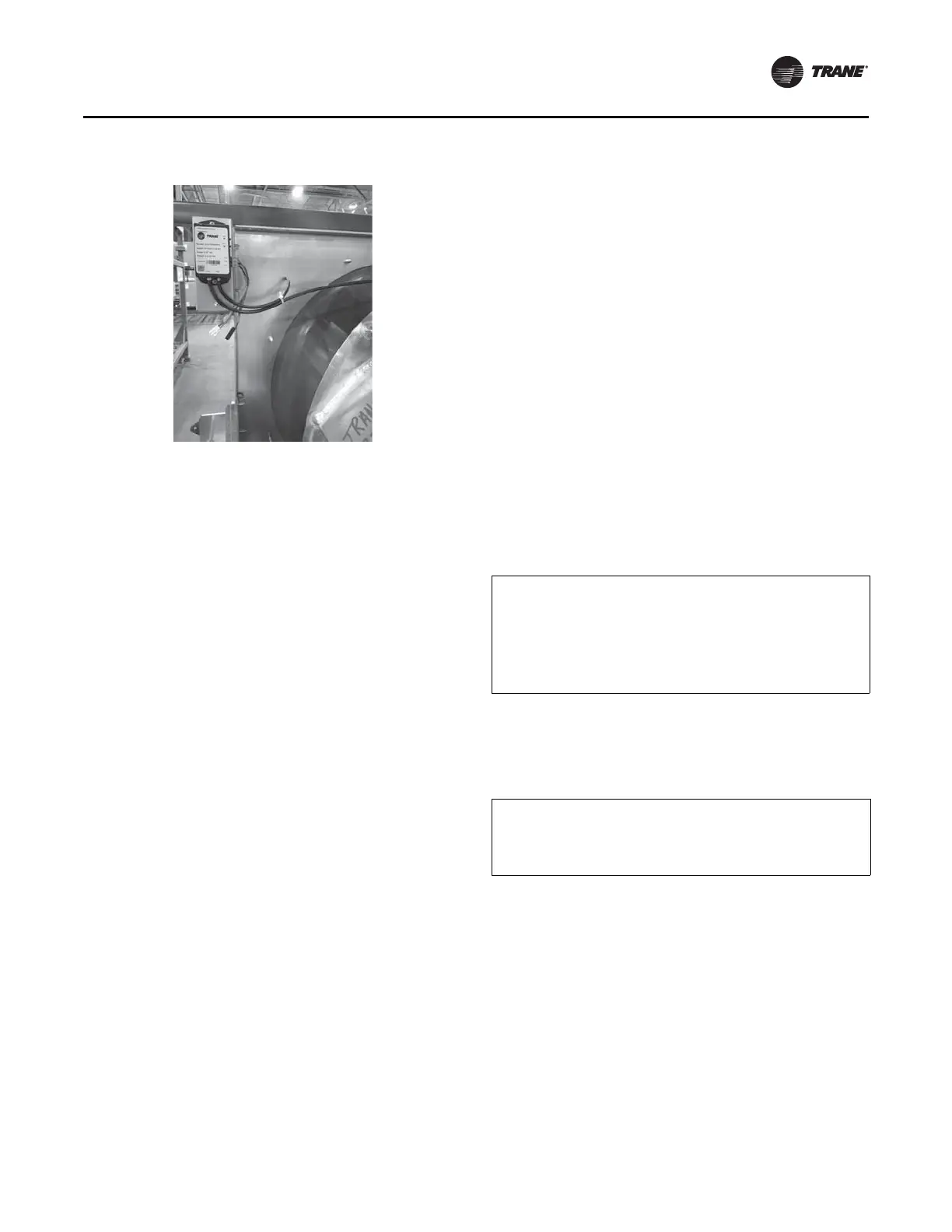
Figure 169. Typical transmitter install for DDP fans
CFM = K * SQRT(DP)
Where:
CFM = Airflow (ft
3
/min.) assuming a standard air density of 0.075
lbm/ft
3
.
K = A constant factor that is unique for each fan. See “Constant Factor
K,” p. 138 for more information.
DP = Differential pressure (inches w.g.) being measured by the
transmitter.
ACFM = CFM * SQRT(0.075/ρ)
Where:
ACFM = Actual airflow (ft
3
/min.) corrected for non-standard air
density.
ρ = Density (lbm/ft
3
) of the air at the inlet to the fan.