Dimensions and Weights
12 CLCH-SVX07K-EN
Table 3. Service clearance dimensions (inches)
Component 3 4 6 8 10 12 14 17 21 25 30 35 40 50 57 66 80 100 120
A (filter) 48484848484848484848484848484852565858
B (coil, humidifier) 48 59 59 66 77 82 87 87 95 95 109 115 128 141 141 156 156 170 197
B (staggered coils) n/a n/a n/a n/a n/a n/a n/a n/a 67 67 76 80 88 96 96 105 105 113 129
C (UV Lights) 48484848484848484848484848484852565858
C (TCACS) 43 59 59 63 75 81 83 83 58 58 83 75 83 83 83 83 83 75 83
D (external motor
control or low
voltage panel)
61 61 61 61 61 61 61 61 64 64 64 64 64 64 64 64 64 64 64
D (internal starter
or VFD)
48 48 48 48 48 48 48 48 48 48 48 48 48 48 48 48 48 48 48
E (fan) 4848484851545861606666667077779393101101
F (gas heat
Ext Vestibule)
n/a n/a 89 90 108 100 100 105 115 115 118 136 140 156 156 170 179 180 n/a
F (gas heat
Int Vestibule)
n/a n/a 56 63 74 79 84 84 92 92 106 112 125 138 138 153 153 167 194
Notes: At a minimum, the above clearance dimensions are recommended on one side of the unit for regular service and maintenance. Refer to as-built
submittal for locations of items such as filter access doors, coil, piping connections, motor locations, hoods, pipe cabinets, etc. Sufficient clearance
must be provided on all sides of unit for removal of access panels, plug panels, or section-to-section attachment brackets. Clearance for starters,
VFDs, or other high-voltage devices must be provided per NEC requirements. For specific dimensional and weight information, refer to the unit
submittals. The dimensions and weights in this manual are approximate. Trane has a policy of continuous product and product data improvement
and reserves the right to change design and specifications without notice.
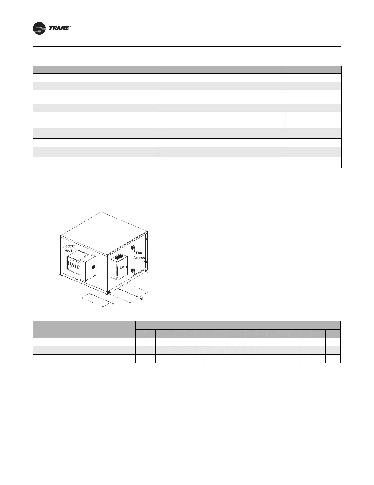
Figure 4. Service clearance for control box
Table 4. Service clearance dimensions (inches) for control box
Component
Unit Size
3 4 6 8 10 12 14 17 21 25 30 35 40 50 57 66 80 100 120
G (LV component - 18 pt term strip)
13 13 13 13 13 13 13 13 13 13 13 13 13 13 13 13 13 13 13
G (LV component - > 18 pt term strip)
36 36 36 36 36 36 36 36 36 36 36 36 36 36 36 36 36 36 36
H (electric heat duct mount)
48 48 48 48 48 48 48 48 48 48 48 n/a n/a n/a n/a n/a n/a n/a n/a